Basic function principles
The analog EL3702/ EL3742 input terminal enables measurement of two voltages/currents, which can be displayed with a resolution of 16 bit (65535 steps).
The oversampling feature enables the terminal to sample analog input values several times during each bus cycle on each channel.
Oversampling
A conventional analog input terminal samples one analog input value ("sample") during each bus cycle and transfers it to the higher-level control system during the next fieldbus cycle. The EL37x2 samples the voltage several times between two fieldbus communication cycles configurable and at equidistant intervals. A 16-bit packet of x analog measured values is transferred to the higher-level control system during the next fieldbus communication cycle. This procedure is referred to as oversampling.
Distributed Clock
Oversampling requires a clock generator in the terminal that triggers the individual data sampling events. The local clock in the terminal, referred to as distributed clock, is used for this purpose.
The distributed clock represents a local clock in the EtherCAT slave controller (ESC) with the following characteristics:
- Unit 1 ns.
- Zero point 1.1.2000 00:00.
- Size 64 bit (sufficient for the next 584 years); however, some EtherCAT slaves only offer 32-bit support, i.e. the variable overflows after approx. 4.2 seconds.
- The EtherCAT master automatically synchronizes the local clock with the master clock in the EtherCAT bus with a precision of < 100 ns.
The EL37x2 only offers 32-bit support.
Sample:
The fieldbus/EtherCAT master is operated with a cycle time of 1 ms to match the higher-level PLC cycle time of 1 ms, for example. This means that every 1 ms an EtherCAT frame is sent to collect the process data from the EL37x2. The local terminal clock therefore triggers an interrupt in the ESC every 1 ms (1 kHz), in order to make the process data available in time for collection by the EtherCAT frame. This first interrupt is called SYNC1.
The EL37x2 may be set to oversampling n = 10 in the TwinCAT System Manager. This causes the ESC to generate a second interrupt in the terminal with an n-times higher frequency, in this case 10 kHz or 100 µs period. This interrupt is called SYNC0. At each SYNC0 signal the analog-to-digital converter (ADC) starts a data sampling event, and the sampled analog values are sequentially stored in a buffer.
 | Determining the input voltages/input currents Both input voltages / input currents (channels 1 and 2) are always sampled simultaneously. This is ensured by the ADC type that is triggered by the SYNC0 pulse. No other operation mode is possible. |
Generation of the SYNC0 pulse from the local synchronized clock within the distributed clock network ensures that the analog values are sampled at highly equidistant intervals with the period of the SYNC1 pulse.
The maximum oversampling factor depends on the memory size of the used ESC and in the KKYY0000 version of the EL37x2, it is n = 100.
| Maximum sampling frequency A smaller period than 10 µs is not permitted for the EL37x2. The maximum sampling frequency for the EL37x2 is therefore 100 kSps (samples per second). Sample: 187,500 µs is permitted, 333.3 is not. |
Sample:
For SYNC1 = 1 ms oversampling factors such as 1,2,5 or 100 are permitted, but not 3! If implausible values are use the terminal will reach the OP state but will not supply any process data. This may result in a working counter error.
The 16-bit measured values accumulated in the buffer are sent as a packet to the higher-level control system. For two channels and n = 100, 2 x 2 x 100 = 400 bytes of process data are transferred during each EtherCAT cycle.
Time-related cooperation with other terminals
ADC data sampling in the EL37x2 is triggered by an interrupt that is generated by the local clock in the terminal. All local clocks in the supporting EtherCAT slaves are synchronized. This enables EtherCAT slaves (here: terminals) to sample measured values simultaneously (simultaneous interrupt generation), independent of the distance between them. This simultaneity is within the distributed clock precision range of < 100 ns.
Sample:
Matching between two EL37x2:
The EtherCAT master, e.g. Beckhoff TwinCAT, configures both EL37x2 such that their SYNC1 signals occur at the same time. Assumption: The EtherCAT bus cycle time is 500 µs. SYNC1 is therefore triggered every 500 µs in all EL37x2. If both terminals operate with a corresponding oversampling factor (e.g. 20), the SYNC0 pulse correlating to SYNC1 will occur simultaneously in all EL37x2, in this example every 25 µs. One application option would be "distributed" oscilloscope with a sampling frequency of 40 kSps, for example.
If the EL37x2 use different oversampling factors, their SYNC0 pulses no longer occur simultaneously. The higher-level SYNC1 pulse is retained.
If a value is entered under "Shift time (µs)" in the TwinCAT System Manager (DC tab, Advanced Settings) for the SYNC0 pulse in an EL37x2, the EL37x2 manipulated in this way will start output sooner or later, according to the set value. This can be useful in cases where a wanted signal has to be sampled at a higher frequency than the 100 kSps permitted for the EL37x2, and several interconnected EL37x2 are therefore used.
Sample:
For sampling a wanted signal at 200 kSps two EL37x2 are used side-by-side and subjected to the same wanted signal (e.g. channel 1 in both terminals). Assume a bus cycle of 1 ms, an oversampling factor in both EL37x2 of n = 100, and therefore maximum speed at 10 µs interval or 100 kSps. In the second EL37x2 an additional Shift Time of 5 µs is entered manually for this terminal in the System Manager (DC tab, Advanced Settings, SYNC0, User Defined). This means all SYNC0 pulses for this EL37x2 will occur 5 µs later than for the first EL37x2.
| Synchronization and provision of process data Since the SYNC1 pulse is derived from the SYNC0 pulse, each SYNC1 pulse of the second EL37x2 will occur 5 µs after the SYNC1 pulse of the first EL37x2. Please note that this may influence the timing of the process data allocation for the EtherCAT frame, since this is controlled by the SYNC1 pulse. |
Each terminal now transfers a 400 byte process data packet to the higher-level control system. If these two data sets (which are offset by 5 µs) with a length of 1 ms each are sorted in the right chronological order in the control system, the wanted signal is transparently sampled at 200 kSps.
The application of these functions using the Beckhoff TwinCAT System Manager is described in section Process data and configuration.
| SYNC0 and SYNC1 pulse with several EtherCAT slaves This approach of matching the SYNC0 and SYNC1 pulses of several EtherCAT slaves is not limited to EL37x2. |
Notice | |
Attention! Risk of device damage! The above notes and information should be used advisedly. |
Timestamp of the process data
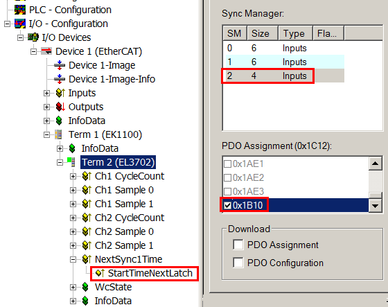
The EL37xx can provide a "timestamp" for each process data block, if required. This process record can be activated as StartTimeNextLatch, a as 32-bit value, by activating 0x1B10 in the Process Data tab, see also Process Data page.
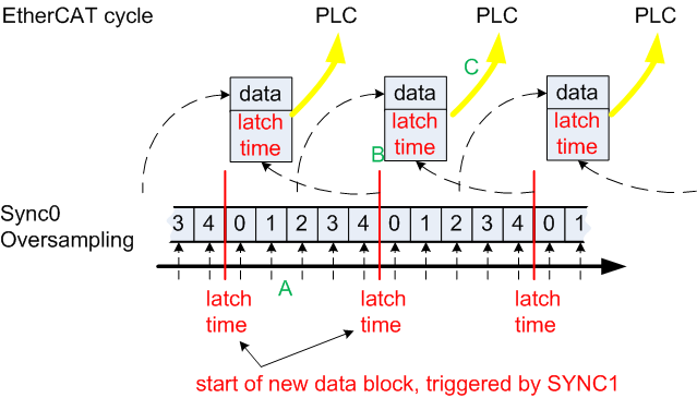
As the name suggests, the data block consisting of sample value+timestamp, which is transferred in each cycle, is not related. The relationship is shown in Fig. Temporal relationship between SYNC signals and SyncManager interrupt. To explain in more detail:
- the example is based on an oversampling factor of 5
- The SYNC0 signal in the terminal triggers the AD conversion and fills the internal buffer with 5 measured values (A).
- SYNC1, which triggers the filled buffer to be made available as process record and at the same time fetches the StartTimeNextLatch from the local distributed clock (B), runs synchronous with the cycle time.
- The data block is linked with the next but one LatchTime.
- The next EtherCAT cycle fetches this data (C).
Process data
Analog values are represented as follows:
|
Input signal |
Value | |
|---|---|---|
|
EL3702 |
Decimal |
Hexadecimal |
|
-10 V |
-32767 |
0x8001 |
|
+10 V |
+32767 |
0x7FFF |
|
Input signal |
Value | |
|---|---|---|
|
EL3742 |
Decimal |
Hexadecimal |
|
0 mA |
0 |
0x0000 |
|
20 mA |
+32767 |
0x7FFF |
The terminal is adjusted during production. No further user intervention is required.
Input characteristics
The input circuit of this terminal is optimized for higher-frequency signals up to around 30 kHz, i.e. the recommended bandwidth of the wanted signal is 0 Hz to 30 kHz in the range -10 V to +10 V or 0 mA to 20 mA. In this frequency range the typical measuring accuracy is as follows:
< 10 Hz < 0.3 % of full-scale value
< 10 kHz < 1 % of full-scale value
< 30 kHz < 4 % of full-scale value
For wanted signals with higher frequencies the signal transducer must have adequately low impedance, in order to prevent amplitude variations (e.g. attenuation in association with simple signal generators) leading to incorrect measurements.
Interference from equipment
This fast analog EtherCAT Terminal may pick up high-frequency superimposed interference signals from other equipment (e.g. proportional valves, stepper motor or DC motor output stages). In order to ensure trouble-free operation, we recommend using separate power supply units for the terminals and the equipment causing interference. The cables should be screened.