Example 1: Diagnosis and evaluation of input data
 Download: (sample file)
 | Usage of this example program This example program was created on a powerful Beckhoff C6920 Industrial PC and requires high computing power. |
- In all tasks, the exceeding counters should not increment and an even utilization should be displayed.
- If an uneven execution of the PLC program is unavoidable, the activation of IoAtTaskBegin should be considered
- You should decrease the buffer size, if necessary, advice regarding this is given below
- If the EL3773 indicates sync errors in the ADS logger window


or in the DiagMessages,
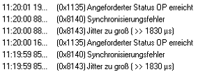
the frames are not arriving regularly at the EL3773. In this case the above points should be checked.
- In particular the synchronization can become more difficult if such effects occur during the start-up phase. This may also prevent the EL3773 from entering the OP state.
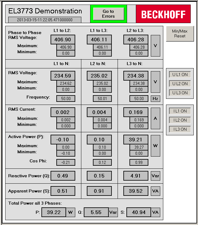 Fig.141: Visualization of example program for EL3773
In this example the input data of an EL3773 will be checked for validity and processed:
- Cycle time and oversampling freely configurable, presetting: 5 ms cycle time, 20-fold oversampling
- WC, State, EtherCAT Master DevState, WcState, FrmState and status of the channels are cyclically checked
- The data from each cycle are placed in a FIFO buffer so that, for example, the evaluation can take place at a higher level. The size of the FIFO buffer is freely configurable
- If all data are valid, the following calculations take place:
- RMS voltage for each channel
- RMS current for each channel
- RMS voltage of the external conductors
- Apparent, active and reactive power for each channel and in total
- Power factor (cos φ) for each phase
- Frequency of each voltage channel
The following list shows an overview of the calculation of the values. More details in the item "Performance of the calculations"
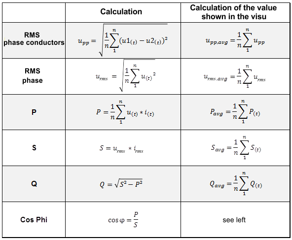 Fig.142: Overview of the performance of the calculations
- The calculations can be switched on and off for each individual channel
- On the basis of the supplied time stamp of the next sample, all other samples are provided with 64 bit DC time stamps; these are necessary for determining the frequency
- Default values are passed on in case of invalid input data; the error which occurred is displayed in the visualization
Connection diagram:
- The wiring is done as described in the chapter Application examples for AC
- The voltage is measured via connections L1, L2, L3 and N.
- The current is measured via three current transformers and the connections IL1, IL2, IL3 and IN (star point of the current transformers).
The program serves as an initial introduction to the options for evaluating the data from a mains monitoring terminal. The user is free to change the program to suit his ideas or to use only part of the code.
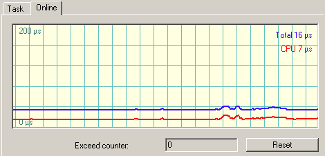
| CPU utilization when using the program The CPU utilization when using the program strongly depends on the selected cycle time and the selected size of the FIFO data buffer. The results of internal company tests have shown that CPU utilization is approximately anti-proportional to the cycle time (i.e. the faster the cycle time, the greater the CPU utilization) and proportional to the size of the FIFO data buffer. The default settings of a 5 ms cycle time and a FIFO size of 800 places resulted in a CPU utilization of about 35% with the following hardware:
|
| Use of the program with the oversampling factor 1 If the operating mode ‘DC Oversampling 1’ is selected in the System Manager, then the PDO assignment 0x1A60 must be activated in the ‘Process Data’ tab for the calculation of the ‘StartTimeNextLatch’. After that the PDO must be linked with the corresponding variable (default: MAIN.fbEL3773.uliStartTimeNextLatch). |