Configuration of 0/4..20 mA differential inputs
This section describes the 0/4..20 mA differential inputs for terminal series EL301x, EL302x, EL311x, EL312x and terminals EL3174, EL3612, EL3742 and EL3751.
For the single-ended 20 mA inputs the terminal series EL304x, EL305x, EL314x, EL315x, EL317x, EL318x and EL375x they only apply with regard to technical transferability and also for devices whose analogue input channels have a common related ground potential (and therefore the channels are not to each other and/or not to power supply electrically isolated). Herewith an example for an electrically isolated device is the terminal EL3174-0002.
Technical background
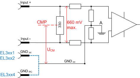
The internal input electronics of the terminals referred to above have the following characteristic (see Fig. Internal connection diagram for 0/4..20 mA inputs):
- Differential current measurement, i.e. concrete potential reference is primarily not required.
The system limit applies is the individual terminal EL30xx/EL31xx. - Current measurement via a 33 Ω shunt per channel, resulting in a maximum voltage drop of 660 mV via the shunt
- Internal resistor configuration with GND point (A) central to the shunt
The configuration of the resistors is symmetric, such that the potential of (A) is central relative to the voltage drop via the shunt. - All channels within the terminal have this GNDint potential in common.
- the common GNDint potential (A)
- is connected for 1 and 2 channel terminals to a terminal point and not with GNDPC (power contact).
- is connected for 4 channel terminals with GNDPC
- The center point of the voltage drop over the 33 Ω shunt is referred to common mode point (CMP).
According to the technical product data, the maximum permitted common mode voltage Vcm refers to the potential between the CMP of a channel and the internal GND or the potential between the CMP of 2 channels within a terminal.
It must not exceed the specified limit (typically ±10 or ±35 V).
Accordingly, for multi-channel measurements Vcm specifications must be followed.
The block diagram for a 2 channel terminal shows the linked GND points within the terminal (Fig. Internal connection for 0/4..20 mA inputs of a EL3xx2):
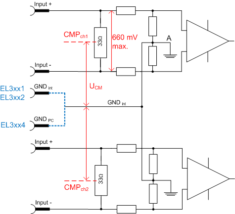
For all channels within the terminal Vcm-max must not be exceeded.
 | Vcm for 0/4..20 mA inputs If Vcm of an analog input channel is exceeded, internal equalizing currents result in erroneous measurements. |
Example 1
The 2-channel EL3012 is connected to 2 sensors, which are supplied with 5 and 24 V. Both current measurements are executed as low-side measurements. This connection type is permitted, because at Imax CMPch1 and CMPch2 are approx. 330 mV above 0 V, which means that Vcm is always < 0.5 V. The requirement of Vcm < 10 V (applicable to EL30xx) is therefore adhered to.
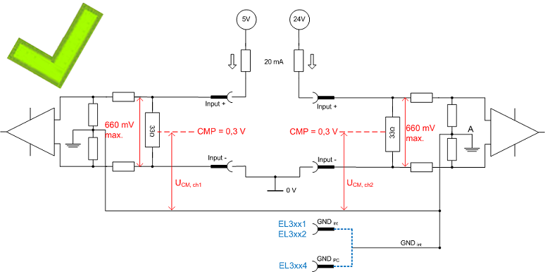
If the EL30x1/EL30x2 or EL31x1/EL31x2 terminals have no external GNDint connection, the GNDint potential can adjust itself as required (referred to as "floating"). Please note that for this mode reduced measuring accuracy is to be expected.
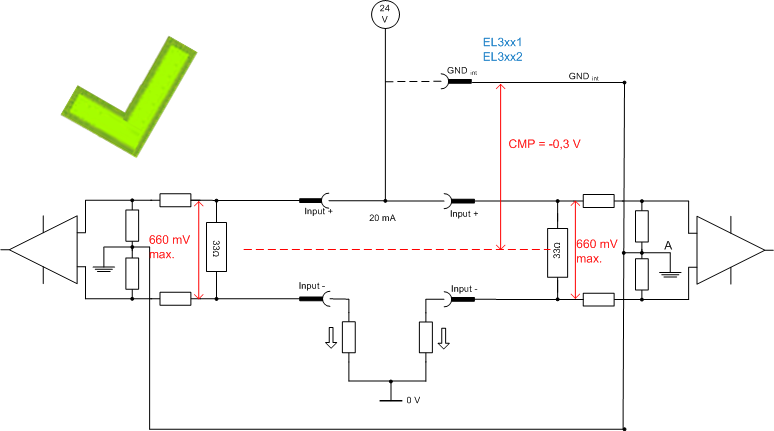
Example 1a
Accordingly, this also applies if the floating point GNDINT is connected to another potential.
Example 2
The same EL3012 is now again connected with the two 20 mA sensors, although this time with one low-side measurement at 5 V and one high-side measurement at 12 V. This results in significant potential differences Vcm > 10 V (applicable to EL30xx) between the two channels, which is not permitted.
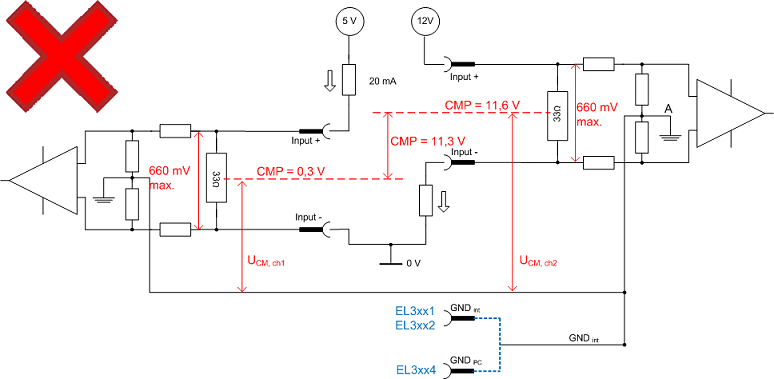
To rectify this, GNDint can in this case be connected externally with an auxiliary potential of 6 V relative to "0 V". The resulting A/GNDint will be in the middle, i.e. approx. 0.3 V or 11.6 V.
Example 3
In the EL3xx4 terminals GNDint is internally connected with the negative power contact. The choice of potential is therefore limited.
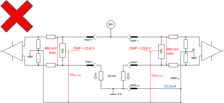
The resulting CMP is 23.6 V, i.e. >> 10 V (applicable to EL30xx). The EL30x4/EL31x4 terminals should therefore be configured such that CMP is always less than Vcm,max.
Summary
This results in certain concrete specifications for external connection with 0/4..20 mA sensors:
- We recommended connecting GNDint with a low-impedance potential, because this significantly improves the measuring accuracy of the EL30xx/31xx.
Please note the instructions relating to the Vcm potential reference. - The Vcm potential reference must be adhered to between CMP ↔ GNDint and CMPch(x) ↔ CMPch(y).
If this cannot be guaranteed, the single-channel version should be used. - Terminal configuration:
- EL3xx1/EL3xx2: GNDint is connected to terminal point for external connection.
GNDint should be connected externally such that condition 2 is met. - EL3xx4: GND is connected with the negative power contact.
The external connection should be such that condition 2 is met.
If the sensor cable is shielded, the shield should not be connected with the GNDint terminal point but with a dedicated low-impedance shield point.
- If terminal points of several EL30xx/EL31xx terminals are connected with each other, ensure that condition 2 is met.
| Connection of GNDint In the EL30x1/EL30x2 and EL31x1/EL31x2 terminals the internal GND, GNDint connection is fed out to terminal contacts. To achieve a precise measurement result GNDint should be connected to a suitable external low-impedance potential, taking account the specifications for Vcm. |