Process data
Introduction
This section describes the individual PDOs and their content. In each case only the first channel is described. The second channel is analogous. The individual PDOs can be activated or deactivated separately in the TwinCAT System Manager. The "Process data" tab is used for this (visible only if the terminal is selected on the left).
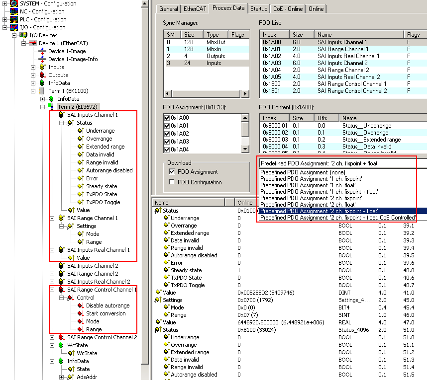 Fig.141: Screenshot of System Manager, Process data
Fig. Screenshot of System Manager, Process data, left, shows the EL3692 with expanded process data, variables of channel 1 are highlighted in red. On the right the process data selection is highlighted in red.
Name of the PDO | Data direction | PDO number channel 1 | PDO number channel 2 |
|---|---|---|---|
SAI Inputs | Input | 0x1A00 | 0x1A03 |
SAI Range | Input | 0x1A01 | 0x1A04 |
SAI Inputs Real | Input | 0x1A02 | 0x1A05 |
SAI Range | Output | 0x1600 | 0x1601 |
Table 1: PDO/channel numbers
 | Measured value display The EL3692 can output the current channel-based measured value depending on the PDO option "Predefined PDO assignment" in 2 different ways. As "fixpoint" and "float". See following explanation: |
- as 32-bit integer measuring range-dependent value, with 24-bit content "fixpoint"
Explanation:
Each of the 9 measuring ranges of the EL3692 extends over 1 decade (e.g. 0 .. 10 Ω). The regular value range of value extends from x0 .. x00 7F FF FF for each measuring range with "x00 7F FF FF ≈ full-scale value". In Autorange mode the measuring range is exceeded by up to 10%, in order to ensure the measuring range changeover. Note the status information.
The following example is for the measuring range 10 Ω:
Input resistance | 32-bit value, right-aligned display | Interpretation | Status bits |
|---|---|---|---|
0 Ω | x00 00 00 00 | 0 | Extended Range = 0 |
10 Ω | x00 7F FF FF | 8.388.607 | Extended Range = 1 |
> 11 Ω | x00 8C CC CB | 9.227.467 | Extended Range = 0 |
Please note that that the relative measuring error is very large near the lower end of the measuring range. For measurements within the range of less than 10% of the lower end of the measuring range the next lower measuring range should be used. The AutoRange function works accordingly.
- as 32-bit fixed-point float-value with mantissa and exponent, measuring range-independent "float"
Explanation:
This 32-bit variable can be linked directly with a FLOAT variable of the PLC according to IEC61131. The conversion takes place in the EL3692; no measuring range-dependent conversion by the user is required.
Predefined PDO Assignment
To simplify the configuration typical configurations based on process data are stored in the EtherCAT XML Device Description. The predefined configurations can be selected in the process data overview. The function is therefore only available if the XML files on the system are current (available for download from the Beckhoff website). The following combinations are possible:
- 1st ch fixpoint only channel 1 measures, no REAL value
- 1st ch float only channel 1 measures, with REAL but no settings
- 1st ch fixpoint + float only channel 1 measures, REAL value and settings
- 2nd ch fixpoint both channels, no REAL value
- 2nd ch float both channels, with REAL but no settings
- 2nd ch fixpoint + float both channels, REAL value and settings (standard)
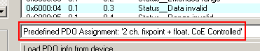 Fig.142: Selection dialog predefined PDO
 | Selection CoE/PDO mode The EL3692 requires an instruction as to whether it should work with or without Autorange etc. This can be set via CoE or the process data (PDO). This distinction is therefore also made via the predefined PDO selection: If the control word is displayed as PDO, the EL3692 primarily responds to the cyclic instructions from the control word. See also Explanations. |
SAI Inputs 0x1A00 (0x1A03)
This PDO contains the status data and the resistance of the terminal. The resistance value is issued as a 32-bit value. The terminal status is shown as WORD.
Name | Explanation | Position, size | Bit in status WORD |
|---|---|---|---|
Status → Underrange | Value below measuring range. | 0x6000:01, 1 bit | SW.0 |
Status → Overrange | Measuring range exceeded. | 0x6000:02, 1 bit | SW.1 |
Status → Extended Range | Extended measuring range is used. | 0x6000:03, 1 bit | SW.2 |
Status → Data invalid | Input data are invalid. | 0x6000:04, 1 bit | SW.3 |
Status → Data invalid | No valid range selected. | 0x6000:05, 1 bit | SW.4 |
Status → Autorange disabled | The Autorange function is disabled. | 0x6000:06, 1 bit | SW.5 |
Status → Error | The error bit is set if the value is invalid (wire breakage, overrange, underrange) | 0x6000:07, 1 bit | SW.6 |
Status → Steady state | If the last four values are no more than x / 1024 of end value apart, the "Steady state" bit is set to TRUE | 0x6000:09, 1 bit | SW.8 |
Status → TxPDO State | Validity of the data of the associated TxPDO (0 = valid, 1 = invalid). | 0x6000:0F, 1 bit | SW.14 |
Status → TxPDO Toggle | The TxPDO toggle is toggled by the slave when the data of the associated TxPDO is updated. | 0x6000:10, 1 bit | SW.15 |
Value | Current measured value as INT32, measuring range end = 0x7F FF FF (standard) | 0x6000:11, 4 bytes | - |
Table 2: Process data 0x1A00
Example Program: Decomposition of WORDS into bits.
SAI Inputs 0x1A01 (0x1A04)
This PDO contains information on the selected measuring mode and the current range. The two values are also available within a settings WORD.
Name | Explanation | Position, size |
|---|---|---|
Mode | Current measuring mode: | 0x6001:05, 4 bit |
Range | Current measuring range | 0x6001:09, 1 byte |
Table 3: Process data 0x1A01
SAI Inputs 0x1A02 (0x1A05)
This PDO contains the current measured value as REAL value. The format matches the REAL format from the TwinCAT PLC Control.
The format matches the REAL format of IEC 61131-3, which in turn is based on the REAL format of IEC 559. A REAL number (single precision) is defined as follows (See also Beckhoff InfoSys: TwinCAT PLC Control: standard data types).
|
Bit position (from left) |
1 |
8 |
23 (+1 "hidden bit", see IE559) |
|
Function |
Sign |
Exponent |
Mantissa |
Table 4: Structure of the REAL value
|
Name |
Explanation |
Position, size |
|---|---|---|
|
Value |
Current measured value as REAL |
0x6002:01, 4 bytes |
Table 5: Process data 0x1A02
SAI Inputs 0x1600 (0x1601)
The terminal can be controlled via this PDO. The data are also available as Control WORD.
Name | Explanation | Position, size | Bit in Control WORD |
|---|---|---|---|
Control → Disable autorange | Request to disable Autorange. | 0x6000:01, 1 bit | CW.0 |
Control → Start conversion | Measurement request (rising edge), only required in single shot mode. | 0x6000:04, 1 bit | CW.3 |
Control → Mode | Current measuring mode: | 0x6001:05, 4 bit | CW.4 - CW.7 |
Control → Range | Current measuring range | 0x6001:09, 1 byte | CW.8 - CW.15 |
Table 6: Process data 0x1600
Example Program: Decomposition of WORDS into bits.