LEDs and connection
This section contains an overview of the terminal, followed by a table with a description of the connection at the terminal.
This is followed by a table with possible LED states.
The following figure shows the terminal overview including the connection options:
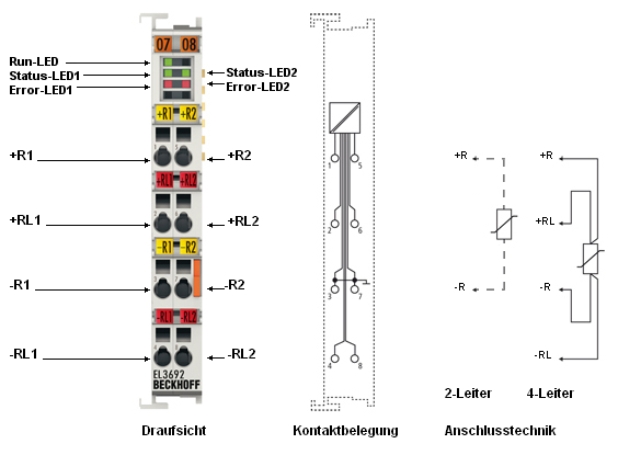 Fig.4: Connection diagram
EL3692 pin assignment
|
Terminal point |
No. |
Comment |
|---|---|---|
|
Input +R1 |
1 |
Input +R1 |
|
Input +RL1 |
2 |
Input +RL1 |
|
Input -R1 |
3 |
Ground (internally connected with terminal point 7) |
|
Input -RL1 |
4 |
Input -RL1 |
|
Input +R2 |
5 |
Input +R2 |
|
Input +RL2 |
6 |
Input +RL2 |
|
Input -R2 |
7 |
Ground (internally connected with terminal point 3) |
|
Input -RL2 |
8 |
Input -RL2 |
LEDs
|
LED |
Color |
Meaning | |
|---|---|---|---|
|
RUN |
green |
This LED indicates the terminal's operating state: | |
|
off |
State of the EtherCAT State Machine: INIT = initialization of the terminal | ||
|
flashing uniformly |
State of the EtherCAT State Machine: PREOP = function for mailbox communication and different standard-settings set | ||
|
flashing slowly |
State of the EtherCAT State Machine: SAFEOP = verification of the sync manager channels and the distributed clocks. | ||
|
on |
State of the EtherCAT State Machine: OP = normal operating state; mailbox and process data communication is possible | ||
|
flashing rapidly |
State of the EtherCAT State Machine: BOOTSTRAP = function for terminal firmware updates | ||
|
STATUS1, STATUS2 |
green |
The respective channel is carrying out a measurement; the test specimen is live. | |
|
ERROR1, ERROR2 |
red |
Wire breakage. The resistance is outside the valid range. | |