Technology
General description
The functionality of the EL3681 is similar to that of a commercial digital multimeter. The terminal offers the following features:
- 1-channel measurement
- AC/DC voltage measurement, range selection automatic through Autorange function or through the controller; measuring ranges 300 mV, 3 V, 30 V, 300 V
- AC/DC current measurement in the 1 A path (internal fuse: 1.25 A) or 10 A path (no internal fuse), measuring ranges: 100 mA, 1 A, 10 A
- Formation of measured values:
AC current/voltage is calculated as a true RMS value without DC component; the signal curve is integrated in the ADC
DC current/voltage is calculated as an arithmetic mean value; the signal curve is integrated in the ADC - Electrical isolation from the fieldbus
- Very good interference immunity through dual-slope conversion technique
- Display of measuring mode (current/voltage) and overload through LED
- Typ. sampling rate approx. 500 ms (2 sps), after change of measuring range up to approx. 1 s (1 sps), with disabled filter approx. 62.5 ms (16 sps)
- The terminal is supplied with a sample program that enables the process data of the EL3681 to be modified and the terminal to be re-parameterized.
The data acquisition is shown in fig. Data flow EL3681.
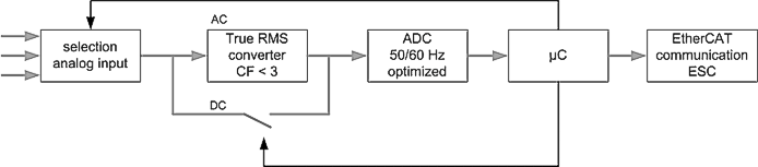 Fig.5: Data flow EL3681
Accuracy
The unused measurement input should be connected to the COM port of the terminal in order to make the analysis as accurate as possible and minimize interference.
- Possible measuring inputs at the terminal:
- Voltage measurement 300 mV – 300 V (connection points 1 + 5)
- Current measurement 100 mA – 1 A (connection point 7)
- Current measurement 10 A (connection point 3)
The measuring accuracy depends on the type of signal to be measured and on the terminal settings.
The accuracy specifications given refer to an input signal in the frequency range >0 ... 1 KHz. With higher frequencies the measuring accuracy decreases (-3 dB >500 kHz).
The accuracy values specified in the following table apply to the default settings for the terminal parameters:
- Enable vendor calibration | true |
- Enable filter | true |
- Frequency | 50 Hz |
- Zero compensation interval | Off (0) |
- Presentation | Scaled (1Bit/1µV) (2) |
Signal to be measured | Typ. max. deviation in % of FSV 1) | typ. temperature drift 2)6) | ||
|---|---|---|---|---|
Measuring mode | Measuring range | 40°C 3) | 0 .. 55°C | ppm/°C |
DC | 3 V - 300 V 8) | 0.01 | 0.2 | 35 |
300 mV 8) | 0.05 | 0.2 | 35 | |
100 mA 7) | 0.1 | 0.5 | 50 | |
1 A | 0.1 | 0.5 | 50 | |
10 A | 0.2 | 1.2 | 170 | |
AC 4) 5) | 3 V - 300 V | 0.25 | 0.75 | 130 |
300 mV | 0.25 | 0.5 | 50 | |
100 mA | 0.5 | 1 | 50 | |
1 A | 0.5 | 0.7 | 50 | |
10 A | 0.5 | 1.2 | 150 | |
Tab. 1: Measuring tolerances as a function of temperatures. FSV = full scale value.
1) In 60 Hz mode of the ADC, add 0.02 to the specified deviation
2) Values apply for a minimum terminal warm-up time of 30 min
3) Adjustment temperature is 40 °C
4) All AC voltage and AC current ranges are specified for the range from 5% to 100%
5) A non-sinusoidal AC input signal can also be measured if it does not exceed a crest factor of 3. The specified accuracy data refer to a crest factor of <= 2
6) In 60 Hz operation, an additional temperature drift of 20 ppm / °C must be expected.
7) The maximum deviation under EMC test conditions according to IEC 61131 is 1 %
8) The maximum deviation under EMC test conditions according to IEC 61131 is 0.2 %
Application note
- To avoid interference, shielded cables must be used for the analog signals. The maximum cable length is 30 m.
- For DC voltage measurements, the AC component must not exceed 150 Vpp.
- For AC voltage measurements, the DC component must not exceed 150 V for sine voltage.
- The peak voltage (relative to the COM terminal) must not exceed 600 V.
- The simultaneous electrical connection of both current paths (10, 1 A) and the voltage path with alternating measurement of the applied variables is technically possible. However, it is not recommended, as there may be crosstalk from one path to the other if there are alternating components in the signals.
Internal resistance
|
Measurement type |
Measuring range |
Internal resistance |
|---|---|---|
|
DC |
300 mV - 300 V |
12.5 MΩ |
|
100 mA - 1 A |
0.2 Ω | |
|
10 A |
3 mΩ | |
|
AC 4) 5) |
300 mV - 300 V |
1 MΩ, approx. 33 pF |
|
100 mA - 1 A |
0.2 Ω | |
|
10 A |
3 mΩ |
Table 2: Internal resistances