Basic principles of IEPE technology
IEPE ("Integrated Electronics Piezo-Electric") is the standardized name for an analog electrical interface between piezoelectric sensors and electronic analysis equipment. Different manufacturers have developed their own brand names, such as ICP®, CCLD®, Isotron®, DeltaTron®, Piezotron®.
Application
Piezoelectric sensors are usually based on a quartz, in which an electrical charge is shifted under mechanical load. The charge can be detected as a voltage if the measurement is made with sufficiently high impedance. The measurement is a preferably static process, which must take place within a much smaller time interval than 10 seconds, since otherwise the charge difference is dissipated through external or internal derivatives. Such a sensor is therefore less suitable for static long-term loads, such as weighing a silo. Such sensors tend to be used for all kinds of predominantly higher frequency vibration measurements (unbalance detection, sound signals via microphones up to ultrasound, mechanical vibrations, foundation monitoring, etc.).
Over the decades, two electrical forms of interfaces to the evaluation unit have developed:
- Direct charge output
- IEPE output
Charge output
The sensor's output signal is provided by a very low change of charge (usually in the range of a little femto to pico coloumb) and tapped by a (possibly short) 2-wire cable. Thus a so called charge amplifier is an essential component of the measurement electronics.
Advantages: the sensor can be exposed to high temperatures over 150 °C; no power supply is required.
Disadvantages: very sensitive to external influences on the cable (line length, possible movement of the cable, type of cable and shielding, electromagnetic fields, etc.); elaborate receiving electronics and cable due to high source impedance.
IEPE output
Since the charging output interface is not generally accepted for industrial applications, a more robust transfer method was sought at an early stage. Thus, for IEPE integrates a field effect transistor (FET) directly at the output of the sensor.
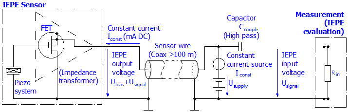
If this sensor is supplied with constant current between 2 and 8 mA via the two-pole cable, the resulting bias voltage is usually approx. 8 to 15 V. If the piezo system is now directly or indirectly (e.g. by a diaphragm) loaded by a measure quantity e.g. force in form of pressure or acceleration, the FET changes its channel resistance caused by change of charge amount on its gate; according to this, a change of the gate source voltage. Because of the supply of Iconst by a constant current source, the bias voltage changes correspondingly by the mechanical load of about few volts. Although the evaluation unit now usually has to provide the constant current supply but is able to deduce the measurement quantity by the back-measured voltage.
Advantages: robust system, which is suitable for operation in industrial conditions.
Disadvantages: upper temperature limit for the sensor 150 to 200 °C, smaller dynamic range.
Notes on constant current
- The higher the feed current, the more the vibration sensor heats up. This may cause a disadvantageous effect on e.g. the basic accuracy of the sensor. For this, note the information provided by the sensor manufacturer.
- The higher the feed current, the higher the maximum transferable signal frequency, since charge inflows and outflows can be balanced more quickly on the cable.
- The higher the supply current, the higher the resulting bias voltage. As a result, the transfer may become more robust against electromagnetic influence, but on the other hand that for large amplitudes the measurement quantity may enter the upper saturation faster.
Notes on the IEPE measuring device
- In some IEPE measuring devices the supply current can be switched off (0 mA), so that they can be used for voltage measurements, cf. for example Beckhoff ELM3604
- Since normally only AC signals are of interest in the vibration range, IEPE evaluations have an electrical high-pass with a cutoff frequency of approximately 10 Hz on the input side. Depending on the application e.g. the capturing of slow tower vibrations, the limit of this high-pass may be relevant, cf. for example the configurable high-pass of the ELM3604, which can be switched off.
- The bias voltage is suitable for detection of wire breakage or short circuit cases respectively, e.g. see also ELM3604 diagnostics options.
Notes on the IEPE sensor
- If IEPE sensors are mounted on high-voltage or frequency converter-controlled motors, an electrically insulated installation or an insulated sensor may be recommendable. In other cases, interference effects on the IEPE measurement have already been observed. This purely functional consideration must be weighed up by the plant installer against normative and electrical safety requirements.