Diagnostics – basic principles of diag messages
DiagMessages designates a system for the transmission of messages from the EtherCAT Slave to the EtherCAT Master/TwinCAT. The messages are stored by the device in its own CoE under 0x10F3 and can be read by the application or the System Manager. An error message referenced via a code is output for each event stored in the device (warning, error, status change).
Definition
The DiagMessages system is defined in the ETG (EtherCAT Technology Group) in the guideline ETG.1020, chapter 13 “Diagnosis handling”. It is used so that pre-defined or flexible diagnostic messages can be conveyed from the EtherCAT Slave to the Master. In accordance with the ETG, the process can therefore be implemented supplier-independently. Support is optional. The firmware can store up to 250 DiagMessages in its own CoE.
Each DiagMessage consists of
- Diag Code (4-byte)
- Flags (2-byte; info, warning or error)
- Text ID (2-byte; reference to explanatory text from the ESI/XML)
- Timestamp (8-byte, local slave time or 64-bit Distributed Clock time, if available)
- Dynamic parameters added by the firmware
The DiagMessages are explained in text form in the ESI/XML file belonging to the EtherCAT device: on the basis of the Text ID contained in the DiagMessage, the corresponding plain text message can be found in the languages contained in the ESI/XML. In the case of Beckhoff products these are usually German and English.
Via the entry NewMessagesAvailable the user receives information that new messages are available.
DiagMessages can be confirmed in the device: the last/latest unconfirmed message can be confirmed by the user.
In the CoE both the control entries and the history itself can be found in the CoE object 0x10F3:
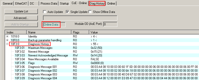
The subindex of the latest DiagMessage can be read under 0x10F3:02.
 | Support for commissioning The DiagMessages system is to be used above all during the commissioning of the plant. The diagnostic values e.g. in the StatusWord of the device (if available) are helpful for online diagnosis during the subsequent continuous operation. |
TwinCAT System Manager implementation
From TwinCAT 2.11 DiagMessages, if available, are displayed in the device’s own interface. Operation (collection, confirmation) also takes place via this interface.
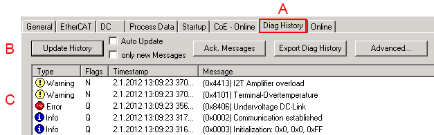
The operating buttons (B) and the history read out (C) can be seen on the Diag History tab (A). The components of the message:
- Info/Warning/Error
- Acknowledge flag (N = unconfirmed, Q = confirmed)
- Time stamp
- Text ID
- Plain text message according to ESI/XML data
The meanings of the buttons are self-explanatory.
DiagMessages within the ADS Logger/Eventlogger
Since TwinCAT 3.1 build 4022 DiagMessages send by the terminal are shown by the TwinCAT ADS Logger. Given that DiagMessages are represented IO- comprehensive at one place, commissioning will be simplified. In addition, the logger output could be stored into a data file – hence DiagMessages are available long-term for analysis.
DiagMessages are actually only available locally in CoE 0x10F3 in the terminal and can be read out manually if required, e.g. via the DiagHistory mentioned above.
In the latest developments, the EtherCAT Terminals are set by default to report the presence of a DiagMessage as emergency via EtherCAT; the event logger can then retrieve the DiagMessage. The function is activated in the terminal via 0x10F3:05, so such terminals have the following entry in the StartUp list by default:
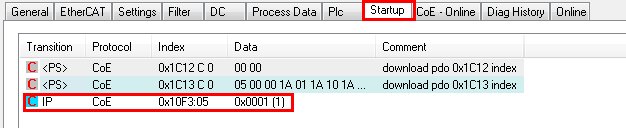
If the function is to be deactivated because, for example, many messages come in or the EventLogger is not used, the StartUp entry can be deleted or set to 0.
Reading messages into the PLC
- In preparation -
Interpretation
Time stamp
The time stamp is obtained from the local clock of the terminal at the time of the event. The time is usually the distributed clock time (DC) from register x910.
Please note: When EtherCAT is started, the DC time in the reference clock is set to the same time as the local IPC/TwinCAT time. From this moment the DC time may differ from the IPC time, since the IPC time is not adjusted. Significant time differences may develop after several weeks of operation without a EtherCAT restart. As a remedy, external synchronization of the DC time can be used, or a manual correction calculation can be applied, as required: The current DC time can be determined via the EtherCAT master or from register x901 of the DC slave.
Structure of the Text ID
The structure of the MessageID is not subject to any standardization and can be supplier-specifically defined. In the case of Beckhoff EtherCAT devices (EL, EP) it usually reads according to xyzz:
x | y | zz |
|---|---|---|
0: Systeminfo | 0: System | Error number |
Example: Message 0x4413 --> Drive Warning Number 0x13
Overview of text IDs
Specific text IDs are listed in the device documentation.
Text ID | Type | Place | Text Message | Additional comment |
|---|---|---|---|---|
0x0001 | Information | System | No error | No error |
0x0002 | Information | System | Communication established | Connection established |
0x0003 | Information | System | Initialization: 0x%X, 0x%X, 0x%X | General information; parameters depend on event. See device documentation for interpretation. |
0x1000 | Information | System | Information: 0x%X, 0x%X, 0x%X | General information; parameters depend on event. See device documentation for interpretation. |
0x1012 | Information | System | EtherCAT state change Init - PreOp |
|
0x1021 | Information | System | EtherCAT state change PreOp - Init |
|
0x1024 | Information | System | EtherCAT state change PreOp - Safe-Op |
|
0x1042 | Information | System | EtherCAT state change SafeOp - PreOp |
|
0x1048 | Information | System | EtherCAT state change SafeOp - Op |
|
0x1084 | Information | System | EtherCAT state change Op - SafeOp |
|
0x1100 | Information | General | Detection of operation mode completed: 0x%X, %d | Detection of the mode of operation ended |
0x1135 | Information | General | Cycle time o.k.: %d | Cycle time OK |
0x1157 | Information | General | Data manually saved (Idx: 0x%X, SubIdx: 0x%X) | Data saved manually |
0x1158 | Information | General | Data automatically saved (Idx: 0x%X, SubIdx: 0x%X) | Data saved automatically |
0x1159 | Information | General | Data deleted (Idx: 0x%X, SubIdx: 0x%X) | Data deleted |
0x117F | Information | General | Information: 0x%X, 0x%X, 0x%X | Information |
0x1201 | Information | Communication | Communication re-established | Communication to the field side restored |
0x1300 | Information | Encoder | Position set: %d, %d | Position set - StartInputhandler |
0x1303 | Information | Encoder | Encoder Supply ok | Encoder power supply unit OK |
0x1304 | Information | Encoder | Encoder initialization successfully, channel: %X | Encoder initialization successfully completed |
0x1305 | Information | Encoder | Sent command encoder reset, channel: %X | Send encoder reset command |
0x1400 | Information | Drive | Drive is calibrated: %d, %d | Drive is calibrated |
0x1401 | Information | Drive | Actual drive state: 0x%X, %d | Current drive status |
0x1705 | Information |
| CPU usage returns in normal range (< 85%%) | Processor load is back in the normal range |
0x1706 | Information |
| Channel is not in saturation anymore | Channel is no longer in saturation |
0x1707 | Information |
| Channel is not in overload anymore | Channel is no longer overloaded |
0x170A | Information |
| No channel range error anymore | A measuring range error is no longer active |
0x170C | Information |
| Calibration data saved | Calibration data were saved |
0x170D | Information |
| Calibration data will be applied and saved after sending the command “0x5AFE” | Calibration data are not applied and saved until the command "0x5AFE" is sent. |
Text ID | Type | Place | Text Message | Additional comment |
|---|---|---|---|---|
0x2000 | Information | System | %s: %s |
|
0x2001 | Information | System | %s: Network link lost | Network connection lost |
0x2002 | Information | System | %s: Network link detected | Network connection found |
0x2003 | Information | System | %s: no valid IP Configuration - Dhcp client started | Invalid IP configuration |
0x2004 | Information | System | %s: valid IP Configuration (IP: %d.%d.%d.%d) assigned by Dhcp server %d.%d.%d.%d | Valid IP configuration, assigned by the DHCP server |
0x2005 | Information | System | %s: Dhcp client timed out | DHCP client timeout |
0x2006 | Information | System | %s: Duplicate IP Address detected (%d.%d.%d.%d) | Duplicate IP address found |
0x2007 | Information | System | %s: UDP handler initialized | UDP handler initialized |
0x2008 | Information | System | %s: TCP handler initialized | TCP handler initialized |
0x2009 | Information | System | %s: No more free TCP sockets available | No free TCP sockets available. |
Text ID | Type | Place | Text Message | Additional comment |
|---|---|---|---|---|
0x4000 | Warning |
| Warning: 0x%X, 0x%X, 0x%X | General warning; parameters depend on event. See device documentation for interpretation. |
0x4001 | Warning | System | Warning: 0x%X, 0x%X, 0x%X |
|
0x4002 | Warning | System | %s: %s Connection Open (IN:%d OUT:%d API:%dms) from %d.%d.%d.%d successful |
|
0x4003 | Warning | System | %s: %s Connection Close (IN:%d OUT:%d) from %d.%d.%d.%d successful |
|
0x4004 | Warning | System | %s: %s Connection (IN:%d OUT:%d) with %d.%d.%d.%d timed out |
|
0x4005 | Warning | System | %s: %s Connection Open (IN:%d OUT:%d) from %d.%d.%d.%d denied (Error: %u) |
|
0x4006 | Warning | System | %s: %s Connection Open (IN:%d OUT:%d) from %d.%d.%d.%d denied (Input Data Size expected: %d Byte(s) received: %d Byte(s)) |
|
0x4007 | Warning | System | %s: %s Connection Open (IN:%d OUT:%d) from %d.%d.%d.%d denied (Output Data Size expected: %d Byte(s) received: %d Byte(s)) |
|
0x4008 | Warning | System | %s: %s Connection Open (IN:%d OUT:%d) from %d.%d.%d.%d denied (RPI:%dms not supported -> API:%dms) |
|
0x4101 | Warning | General | Terminal-Overtemperature | Overtemperature. The internal temperature of the terminal exceeds the parameterized warning threshold. |
0x4102 | Warning | General | Discrepancy in the PDO-Configuration | The selected PDOs do not match the set operating mode. Sample: Drive operates in velocity mode, but the velocity PDO is but not mapped in the PDOs. |
0x417F | Warning | General | Warning: 0x%X, 0x%X, 0x%X |
|
0x428D | Warning | General | Challenge is not Random |
|
0x4300 | Warning | Encoder | Subincrements deactivated: %d, %d | Sub-increments deactivated (despite activated configuration) |
0x4301 | Warning | Encoder | Encoder-Warning | General encoder error |
0x4302 | Warning | Encoder | Maximum frequency of the input signal is nearly reached (channel %d) |
|
0x4303 | Warning | Encoder | Limit counter value was reduced because of the PDO configuration (channel %d) |
|
0x4304 | Warning | Encoder | Reset counter value was reduced because of the PDO configuration (channel %d) |
|
0x4400 | Warning | Drive | Drive is not calibrated: %d, %d | Drive is not calibrated |
0x4401 | Warning | Drive | Starttype not supported: 0x%X, %d | Start type is not supported |
0x4402 | Warning | Drive | Command rejected: %d, %d | Command rejected |
0x4405 | Warning | Drive | Invalid modulo subtype: %d, %d | Modulo sub-type invalid |
0x4410 | Warning | Drive | Target overrun: %d, %d | Target position exceeded |
0x4411 | Warning | Drive | DC-Link undervoltage (Warning) | The DC link voltage of the terminal is lower than the parameterized minimum voltage. Activation of the output stage is prevented. |
0x4412 | Warning | Drive | DC-Link overvoltage (Warning) | The DC link voltage of the terminal is higher than the parameterized maximum voltage. Activation of the output stage is prevented. |
0x4413 | Warning | Drive | I2T-Model Amplifier overload (Warning) |
|
0x4414 | Warning | Drive | I2T-Model Motor overload (Warning) |
|
0x4415 | Warning | Drive | Speed limitation active | The maximum speed is limited by the parameterized objects (e.g. velocity limitation, motor speed limitation). This warning is output if the set velocity is higher than one of the parameterized limits. |
0x4416 | Warning | Drive | Step lost detected at position: 0x%X%X | Step loss detected |
0x4417 | Warning | Drive | Motor overtemperature | The internal temperature of the motor exceeds the parameterized warning threshold |
0x4418 | Warning | Drive | Limit: Current | Limit: current is limited |
0x4419 | Warning | Drive | Limit: Amplifier I2T-model exceeds 100%% | The threshold values for the maximum current were exceeded. |
0x441A | Warning | Drive | Limit: Motor I2T-model exceeds 100%% | Limit: Motor I2T-model exceeds 100% |
0x441B | Warning | Drive | Limit: Velocity limitation | The threshold values for the maximum speed were exceeded. |
0x441C | Warning | Drive | STO while the axis was enabled | An attempt was made to activate the axis, despite the fact that no voltage is present at the STO input. |
0x4600 | Warning | General IO | Wrong supply voltage range | Supply voltage not in the correct range |
0x4610 | Warning | General IO | Wrong output voltage range | Output voltage not in the correct range |
0x4705 | Warning |
| Processor usage at %d %% | Processor load at %d %% |
0x470A | Warning |
| EtherCAT Frame missed (change Settings or DC Operation Mode or Sync0 Shift Time) | EtherCAT frame missed (change DC Operation Mode or Sync0 Shift Time under Settings) |
Text ID | Type | Place | Text Message | Additional comment |
|---|---|---|---|---|
0x8000 | Error | System | %s: %s |
|
0x8001 | Error | System | Error: 0x%X, 0x%X, 0x%X | General error; parameters depend on event. See device documentation for interpretation. |
0x8002 | Error | System | Communication aborted | Communication aborted |
0x8003 | Error | System | Configuration error: 0x%X, 0x%X, 0x%X | General; parameters depend on event. See device documentation for interpretation. |
0x8004 | Error | System | %s: Unsuccessful FwdOpen-Response received from %d.%d.%d.%d (%s) (Error: %u) |
|
0x8005 | Error | System | %s: FwdClose-Request sent to %d.%d.%d.%d (%s) |
|
0x8006 | Error | System | %s: Unsuccessful FwdClose-Response received from %d.%d.%d.%d (%s) (Error: %u) |
|
0x8007 | Error | System | %s: Connection with %d.%d.%d.%d (%s) closed |
|
0x8100 | Error | General | Status word set: 0x%X, %d | Error bit set in the status word |
0x8101 | Error | General | Operation mode incompatible to PDO interface: 0x%X, %d | Mode of operation incompatible with the PDO interface |
0x8102 | Error | General | Invalid combination of Inputs and Outputs PDOs | Invalid combination of input and output PDOs |
0x8103 | Error | General | No variable linkage | No variables linked |
0x8104 | Error | General | Terminal-Overtemperature | The internal temperature of the terminal exceeds the parameterized error threshold. Activation of the terminal is prevented |
0x8105 | Error | General | PD-Watchdog | Communication between the fieldbus and the output stage is secured by a Watchdog. The axis is stopped automatically if the fieldbus communication is interrupted.
|
0x8135 | Error | General | Cycle time has to be a multiple of 125 µs | The IO or NC cycle time divided by 125 µs does not produce a whole number. |
0x8136 | Error | General | Configuration error: invalid sampling rate | Configuration error: Invalid sampling rate |
0x8137 | Error | General | Electronic type plate: CRC error | Content of the external name plate memory invalid. |
0x8140 | Error | General | Sync Error | Real-time violation |
0x8141 | Error | General | Sync%X Interrupt lost | Sync%X Interrupt lost |
0x8142 | Error | General | Sync Interrupt asynchronous | Sync Interrupt asynchronous |
0x8143 | Error | General | Jitter too big | Jitter limit violation |
0x817F | Error | General | Error: 0x%X, 0x%X, 0x%X |
|
0x8200 | Error | Communication | Write access error: %d, %d | Error while writing |
0x8201 | Error | Communication | No communication to field-side (Auxiliary voltage missing) |
|
0x8281 | Error | Communication | Ownership failed: %X |
|
0x8282 | Error | Communication | To many Keys founded |
|
0x8283 | Error | Communication | Key Creation failed: %X |
|
0x8284 | Error | Communication | Key loading failed |
|
0x8285 | Error | Communication | Reading Public Key failed: %X |
|
0x8286 | Error | Communication | Reading Public EK failed: %X |
|
0x8287 | Error | Communication | Reading PCR Value failed: %X |
|
0x8288 | Error | Communication | Reading Certificate EK failed: %X |
|
0x8289 | Error | Communication | Challenge could not be hashed: %X |
|
0x828A | Error | Communication | Tickstamp Process failed |
|
0x828B | Error | Communication | PCR Process failed: %X |
|
0x828C | Error | Communication | Quote Process failed: %X |
|
0x82FF | Error | Communication | Bootmode not activated | Boot mode not activated |
0x8300 | Error | Encoder | Set position error: 0x%X, %d | Error while setting the position |
0x8301 | Error | Encoder | Encoder increments not configured: 0x%X, %d | Encoder increments not configured |
0x8302 | Error | Encoder | Encoder error | The amplitude of the resolver is too small |
0x8303 | Error | Encoder | Encoder power missing (channel %d) |
|
0x8304 | Error | Encoder | Encoder communication error, channel: %X | Encoder communication error |
0x8305 | Error | Encoder | EnDat2.2 is not supported, channel: %X | EnDat2.2 is not supported |
0x8306 | Error | Encoder | Delay time, tolerance limit exceeded, 0x%X, channel: %X | Runtime measurement, tolerance exceeded |
0x8307 | Error | Encoder | Delay time, maximum value exceeded, 0x%X, channel: %X | Runtime measurement, maximum value exceeded |
0x8308 | Error | Encoder | Unsupported ordering designation, 0x%X, channel: %X (only 02 and 22 is supported) | Wrong EnDat order ID |
0x8309 | Error | Encoder | Encoder CRC error, channel: %X | Encoder CRC error |
0x830A | Error | Encoder | Temperature %X could not be read, channel: %X | Temperature cannot be read |
0x830C | Error | Encoder | Encoder Single-Cycle-Data Error, channel. %X | CRC error detected. Check the transmission path and the CRC polynomial |
0x830D | Error | Encoder | Encoder Watchdog Error, channel. %X | The sensor has not responded within a predefined time period |
0x8310 | Error | Encoder | Initialisation error |
|
0x8311 | Error | Encoder | Maximum frequency of the input signal is exceeded (channel %d) |
|
0x8312 | Error | Encoder | Encoder plausibility error (channel %d) |
|
0x8313 | Error | Encoder | Configuration error (channel %d) |
|
0x8314 | Error | Encoder | Synchronisation error |
|
0x8315 | Error | Encoder | Error status input (channel %d) |
|
0x8400 | Error | Drive | Incorrect drive configuration: 0x%X, %d | Drive incorrectly configured |
0x8401 | Error | Drive | Limiting of calibration velocity: %d, %d | Limitation of the calibration velocity |
0x8402 | Error | Drive | Emergency stop activated: 0x%X, %d | Emergency stop activated |
0x8403 | Error | Drive | ADC Error | Error during current measurement in the ADC |
0x8404 | Error | Drive | Overcurrent | Overcurrent in phase U, V or W |
0x8405 | Error | Drive | Invalid modulo position: %d | Modulo position invalid |
0x8406 | Error | Drive | DC-Link undervoltage (Error) | The DC link voltage of the terminal is lower than the parameterized minimum voltage. Activation of the output stage is prevented. |
0x8407 | Error | Drive | DC-Link overvoltage (Error) | The DC link voltage of the terminal is higher than the parameterized maximum voltage. Activation of the output stage is prevented. |
0x8408 | Error | Drive | I2T-Model Amplifier overload (Error) |
|
0x8409 | Error | Drive | I2T-Model motor overload (Error) |
|
0x840A | Error | Drive | Overall current threshold exceeded | Total current exceeded |
0x8415 | Error | Drive | Invalid modulo factor: %d | Modulo factor invalid |
0x8416 | Error | Drive | Motor overtemperature | The internal temperature of the motor exceeds the parameterized error threshold. The motor stops immediately. Activation of the output stage is prevented. |
0x8417 | Error | Drive | Maximum rotating field velocity exceeded | Rotary field speed exceeds the value specified for dual use (EU 1382/2014). |
0x841C | Error | Drive | STO while the axis was enabled | An attempt was made to activate the axis, despite the fact that no voltage is present at the STO input. |
0x8550 | Error | Inputs | Zero crossing phase %X missing | Zero crossing phase %X missing |
0x8551 | Error | Inputs | Phase sequence Error | Wrong direction of rotation |
0x8552 | Error | Inputs | Overcurrent phase %X | Overcurrent phase %X |
0x8553 | Error | Inputs | Overcurrent neutral wire | Overcurrent neutral wire |
0x8581 | Error | Inputs | Wire broken Ch %D | Wire broken Ch %d |
0x8600 | Error | General IO | Wrong supply voltage range | Supply voltage not in the correct range |
0x8601 | Error | General IO | Supply voltage to low | Supply voltage too low |
0x8602 | Error | General IO | Supply voltage to high | Supply voltage too high |
0x8603 | Error | General IO | Over current of supply voltage | Overcurrent of supply voltage |
0x8610 | Error | General IO | Wrong output voltage range | Output voltage not in the correct range |
0x8611 | Error | General IO | Output voltage to low | Output voltage too low |
0x8612 | Error | General IO | Output voltage to high | Output voltage too high |
0x8613 | Error | General IO | Over current of output voltage | Overcurrent of output voltage |
0x8700 | Error |
| Channel/Interface not calibrated | Channel/interface not synchronized |
0x8701 | Error |
| Operating time was manipulated | Operating time was manipulated |
0x8702 | Error |
| Oversampling setting is not possible | Oversampling setting not possible |
0x8703 | Error |
| No slave controller found | No slave controller found |
0x8704 | Error |
| Slave controller is not in Bootstrap | Slave controller is not in bootstrap |
0x8705 | Error |
| Processor usage to high (>= 100%%) | Processor load too high (>= 100%%) |
0x8706 | Error |
| Channel in saturation | Channel in saturation |
0x8707 | Error |
| Channel overload | Channel overload |
0x8708 | Error |
| Overloadtime was manipulated | Overload time was manipulated |
0x8709 | Error |
| Saturationtime was manipulated | Saturation time was manipulated |
0x870A | Error |
| Channel range error | Measuring range error for the channel |
0x870B | Error |
| no ADC clock | No ADC clock available |
0xFFFF | Information |
| Debug: 0x%X, 0x%X, 0x%X | Debug: 0x%X, 0x%X, 0x%X |