U/I Mapping
The problem often arises that the voltages U1, U2, and U3 and the currents Ia, Ib and Ic are connected to a power meter and it must then be determined which voltage corresponds to which current. Formally, the goal is to find a bijective mapping between currents Ia, Ib and Ic to voltages U1, U2, and U3. Since this problem cannot generally be solved (except by tracing the cables), the following assumptions have to be made:
- Right-hand rotation field
- Power flow is either feeding in or consuming
From the assumptions, it follows that the angle between current and voltage is only a maximum of 90 degrees. Therefore, the phases of the resulting currents of the voltages U1, U2, and U3 lie in the following ranges:
-90° ≤ φI1 ≤ 90°
-210° ≤ φI2 ≤ -30°
30° ≤ φI3 ≤ 210°
This results in areas that are exclusive to some phases and others that are shared by two subsequent phases:
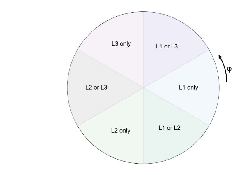 Fig.21: EL3475 - U/I mapping, Phases
The respective relationship between current and voltage can then be derived from these areas using a process of elimination.
Example
Let us assume three currents Ia, Ib and Ic having the following phases:
φa = 0°
φb = -90°
φc = 150°
The mapping a = L1 is unique.
Since IL1 is already determined, Ib is mapped to L2.
Finally, c = 3 can be determined.