Application examples for alternating current
Power measurement at a machine
- The voltage is measured via connections L1, L2, L3 and N.
- The current is measured via three current transformers and the connections IL1, IL2, IL3 and IN (star point of the current transformers).
| |
WARNING: Risk of electric shock! Bring the Bus Terminals system into a safe, de-energized state before starting mounting, disassembly or wiring of the Bus Terminals. |

Notice | |
Attention! Risk of device damage! Avoid confusing the current and voltage circuit during connection, since the direct connection of mains voltage to the terminal points for the current transformers (typical input resistance 220 mΩ) would destroy the power measurement terminal! |
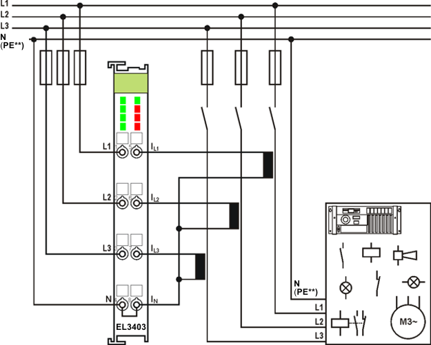 Fig.141: Power measurement at a machine
 | **) PE as star point for 3-phase systems without neutral line Depending on the current transformers used, PE must be connected as star point in 3-phase systems without neutral line as shown in Fig. “Power measurement at a machine ". Observe the regulations of the manufacturer of the current transformers! |
| Negative power values If negative power values are measured on a circuit, please check whether the associated current transformer circuit is connected correctly. |
| Current measurement A current measurement requires a voltage source to be connected. A current measurement is not possible without voltage source. |
Power measurement on motor with 2 current transformers
- The voltage is measured via the connections L1, L2 and L3.
- The current is measured with two current transformers via the connections IL1 and IL2.
- The sum of all currents in the 3-phase mains network is 0. The value in circuit IL3 can be obtained accordingly by wiring the EL3403.
| |
WARNING: Risk of electric shock! If you do not connect terminal point N with the neutral conductor of your mains supply, you have to earth terminal point N, in order to avoid dangerous overvoltages in the event of a fault with a current transformer! |
Notice | |
Attention! Risk of device damage! Avoid confusing the current and voltage circuit during connection, since the direct connection of mains voltage to the terminal points for the current transformers (typical input resistance 220 mΩ) would destroy the power measurement terminal! |
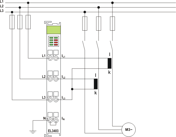 Fig.142: Power measurement with 2 current transformers on a motor
In the circuit shown above (Fig. Power measurement with 2 current transformers on a motor), ensure that the three-phase system is either earth-free is or has an earthed star point. Alternatively a transformer can be included in a Yy0 circuit.
Power measurement in a single-phase mains network with ohmic consumers
- The voltage is measured via connections L1, L2, L3 and N.
- The current is measured via three current transformers and the connections IL1, IL2, IL3 and IN (star point of the current transformers).
| |
WARNING: Risk of electric shock! Bring the Bus Terminals system into a safe, de-energized state before starting mounting, disassembly or wiring of the Bus Terminals. |
Notice | |
Attention! Risk of device damage! Avoid confusing the current and voltage circuit during connection, since the direct connection of mains voltage to the terminal points for the current transformers (typical input resistance 220 mΩ) would destroy the power measurement terminal! |
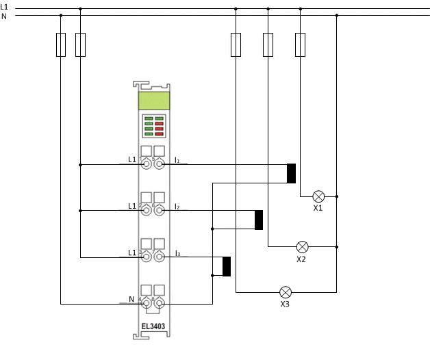 Fig.143: Power measurement at ohmic consumers