EL3403 - LEDs and connection
| |
Caution: Risk of electric shock! If you do not connect the terminal point N with the neutral conductor of your mains supply (e.g. if the KL3403 is used purely for current measurements), terminal point N should be earthed, in order to avoid dangerous overvoltages in the event of a current transformer fault! |

| |
Caution: Risk of electric shock! Please note that many manufacturers do not permit their current transformers to be operated in no-load mode! Connect the EL3403 to the secondary windings of the current transformers before using the current transformer! |
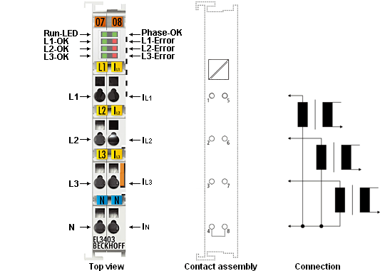
EL3403-xxxx - Connection
|
Terminal point |
Description |
Comment | |
|---|---|---|---|
|
Name |
No. | ||
|
L1 |
1 |
Phase L1 |
Connections for the voltage measurement |
|
L2 |
2 |
Phase L2 | |
|
L3 |
3 |
Phase L3 | |
|
N |
4 |
Neutral conductor N | |
|
IL1 |
5 |
Consumer at phase L1 |
Connections for the current transformers. Note the warnings - " Caution: Risk of electric shock! " |
|
IL2 |
6 |
Consumer at phase L2 | |
|
IL3 |
7 |
Consumer at phase L3 | |
|
IN |
8 |
Star point of the current transformers | |
EL3403-xxxx - LEDs
|
LED |
Color |
Meaning | |
|---|---|---|---|
|
RUN |
green |
This LED indicates the terminal's operating state: | |
|
off |
State of the EtherCAT State Machine: INIT = initialization of the terminal or BOOTSTRAP = function for firmware updates of the terminal | ||
|
flashing |
State of the EtherCAT State Machine: PREOP = function for mailbox communication and different standard-settings set | ||
|
single flash |
State of the EtherCAT State Machine: SAFEOP = verification of the Sync Manager channels and the distributed clocks. | ||
|
on |
State of the EtherCAT State Machine: OP = normal operating state; mailbox and process data communication is possible | ||
|
Phase-OK |
green |
off |
Clockwise rotary field |
|
on |
Counter-clockwise rotary field | ||
|
L1-OK |
green |
on |
Voltage on L1 and zero crossing detected |
|
L1-Error |
red |
on |
No voltage detected at L1 |
|
L2-OK |
green |
on |
Voltage on L2 and zero crossing detected |
|
L2-Error |
red |
on |
No voltage detected at L2 |
|
L3-OK |
green |
on |
Voltage on L3 and zero crossing detected |
|
L3-Error |
red |
on |
No voltage detected at L3 |
UL compliance
In addition to the information in the Appendix, the following notes are relevant in relation to compliance with Underwriters Laboratories specifications.
NOTICE | ||
 | Phase voltage according to UL specifications 300 V max. The maximum phase voltage of 500 V described in the technical data should be limited to 300 V for applications requiring UL approval. | |
NOTICE | ||
| Current transformer Current measurement inputs with the IDs IL1, IL2, IL3, N may only be connected to isolating current transformers, which limit the available current to max. 5 A, 20 V. | |