Basic function principles
Measuring principle
The EL3403 works with 6 analog/digital converters for recording the current and voltage values of all 3 phases.
Recording and processing is synchronous and identical for the 3 phases. The signal processing for one phase is described below. This description applies correspondingly for all 3 phases.
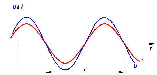 Fig.5: Voltage u and current i curves
RMS value calculation
The rms value for voltage and current is calculated over a measuring interval, in this case the period T. The following equations are used:
u(t): instantaneous voltage value
i(t): instantaneous current value
n: number of measured values
Measuring interval
The choice of the right measuring interval is important for the quality of the measurement. The default setting for the measuring interval is 10 periods (10 x 20 ms). Experience shows that this is a good compromise between measuring speed and stability. Deviations from this value are only advisable in the event of particular measurement requirements (e.g. high measuring speed).
Effective power measurement
The EL3403 measures the effective power P according to the following equation
P: Effective power
n: Number of samples
u(t): Instantaneous voltage value
i(t): Instantaneous current value
 Fig.6: Power s (t) curve
In the first step, the power s(t) is calculated at each sampling instant:
The mean value over the measuring interval is calculated. Here too, the correct choice of the intervals is important, as described in section RMS value measurement (the interval can only be changed simultaneously for U, I and P).
The power frequency is twice that of the corresponding voltages and currents.
Apparent power measurement
In real networks, not all consumers are purely ohmic. Phase shifts occur between current and voltage. This does not affect the methodology for determining the rms values of voltage and current as described above.
The situation for the effective power is different: Here, the product of effective voltage and effective current is the apparent power.
The effective power is smaller than the apparent power.
S: Apparent power
P: Effective power
Q: Reactive power
φ: Phase shift angle
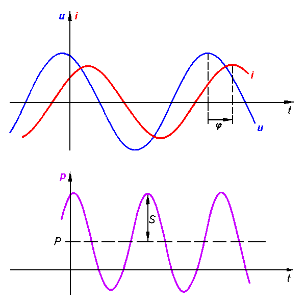 Fig.7: u, i, p curves with phase shift angle (t) (t) (t) j
In this context, further parameters of the mains system and its consumers are significant:
- apparent power S
- reactive power Q
- power factor cos φ
The EL3403 determines the following values:
- effective power P
- effective voltage U
- effective current I
- apparent power S
- reactive power Q
- power factor cos φ
Sign for power measurement
The sign of the active power P and of the power factor cos φ provide about information the direction of the energy flow. A positive sign indicates the motor mode, a negative sign indicates generator mode.
In addition, the sign of the reactive power Q indicates the direction of the phase shift between current and voltage. Fig. Four-quadrant representation of active/reactive power in motor and generator mode illustrates this. In motor mode (quadrant I & IV) a positive reactive power indicates an inductive load, a negative reactive power indicates a capacitive load. In generator mode (quadrant II & III), an inductive acting generator is indicated by a positive reactive power, a capacitive acting generator by a negative reactive power.
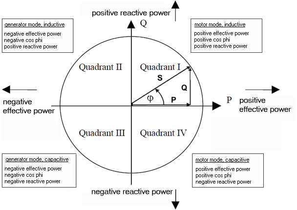 Fig.8: Four-quadrant representation of active/reactive power in motor and generator mode
Frequency measurement
The EL3403 can measure the frequency of the input signals at a voltage circuit (L1, L2 or L3).