Connection diagram
5 V can be taken directly from the terminal to supply the resistor bridge. For this case the resulting connection diagram (Fig. Connection of a load cell with 5 V supply via the EL3351) is:
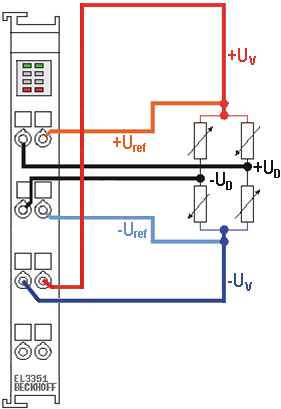 Fig.147: Connection of a load cell with 5 V supply via the EL3351
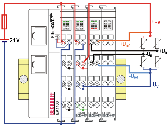 Fig.148: Connection of a load cell with 10 V supply via the EL9510
Beckhoff offers various power supply terminals for the supply of power to the load cells of an EL3351:
|
Power supply terminal |
Input voltage |
Output voltage |
Output current |
|---|---|---|---|
|
EL9505 |
24 VDC |
5 VDC ±1% |
0.5 A |
|
EL9508 |
24 VDC |
8 VDC ±1% |
0.5 A |
|
EL9510 |
24 VDC |
10 VDC ±1% |
0.5 A |
|
EL9512 |
24 VDC |
12 VDC ±1% |
0.5 A |
 | Observe the specifications for the voltage supply to the load cells! The specifications given by the load cell manufacturer for the maximum supply voltage must be observed! |
| Observe the specifications for the parallel connection of the load cells! The specifications given by the load cell manufacturer for the parallel connection must be observed! In principle, load cells connected in parallel must have the same nominal characteristic value, the same nominal load and the same internal resistance. |