Application example: load cell
The following example shows the connection of a full bridge with external 10V supply and the calculation of the weight value in the control.
Connection of the load cell
The EL9510 power supply terminal with 10 V is used to supply the 350 Ω full bridge. The full bridge is therefore supplied with UV = 10 V. The current flow causes a voltage drop on the supply lines (red, dark blue) to the measuring bridge, so that URef < UV returns to the EL3351 on the sense lines (orange, light blue). Since URef and UDiff are the "true" voltages acting at the measuring bridge, these must be measured and used for the calculated evaluation.
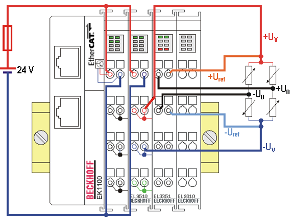
Connection of a load cell with 10 V supply via the EL9510
 | Parallel connection of load cells If several load cells are connected in parallel to the EL3351 and the internal 5V supply is used, the total current consumption must be observed. It must not exceed the specified maximum output current. Only load cells that are appropriately calibrated and approved for this operation may be used. |
Further calculation in the controller (TwinCAT)
| Calibration of the system Before the measured value calculation, a calibration of the entire system is required due to the tolerances of the load cells/force transducers. This calibration must be carried out with a reference weight! |
UDiff and URef are transported to the controller as INT values via the EtherCAT process data of the EL3351. The voltage values are to be calculated there according to
UDiff [mV] = PDO "Ch. 1 valuedec" x (20 mV / 2147483647dec)
URef [V] = PDO "Ch. 2 valuedec" x (12 V / 2147483647dec)
The gross weight calculation (incl. scale tare weight) is then done according to
YR = (UDiff / URef) x (Emax / Cn)
with
Name | Designation | Unit |
|---|---|---|
UDiff | Measuring signal of the load cell (differential voltage), max. 12 V | [1] |
URef | Reference signal of the load cell (supply voltage), max. 20 mV | [1] |
Emax | Nominal load of the load cell, e.g. 50 kg | [1 kg] |
Cn | Characteristic value of the load cell, e.g. 2.013 mV/V | [1 mV / V] |
Any necessary corrective interventions (tare, adjustment, zero) must then be made on the control side on YR.
Concrete example in numbers:
Data of the sensor
- Characteristic value Cn = 2 mV / V
- Nominal load Emax = 50 kg
- Supply voltage UV = 10 V
Weight calculation
At full load (load cell is loaded with 50 kg) UDiff_max is calculated to:
UDiff_max = URef_max x Cn = 10 V x 2 (mV / V) = 20 mV
Assumption: With G = 7 kg load
UDiff = UDiff_max / Emax x G = 20 mV / 50 kg x 7 kg = 2,8 mV
Fictitious measured values
- Bridge: „value1“ (Inputs bridge) = 0x11EB7026 = 300.642.342dec
- Supply: „value2“ (Inputs supply) = 0x6AA9D8F2 = 1.789.516.018dec
Calculation of the voltages with the measured values
UDiff = 300642342dec x (20 mV / 2147483647) = 2,79995 mV
URef = 1789516018dec x (12 V / 2147483647) = 9,9997 V
G = UDiff / URef x Emax / Cn = 2,79995 mV / 9,9997 V x 50 kg / 2(mV / V)) = 7,00009 kg