Thermocouple measurement with Beckhoff
Thermocouple specification and conversion
Temperature measurement with thermocouples generally comprises three steps:
- Measuring the electrical voltage,
- optional: Temperature measurement of the internal cold junction,
- optional: Software-based conversion of the voltage into a temperature value according to the set thermocouple type (K, J, …).
All three steps can take place locally in the Beckhoff measuring device. Device-based transformation can be disabled if the conversion is to take place in the higher-level control system. Depending on the device type, several thermocouple conversions are available, which differ in terms of their software implementation.
For Beckhoff thermocouple measuring devices this means that
- a specification of the electrical voltage measurement is provided and
- based on this, the effect on temperature measurement is specified depending on the supported thermocouple type. Note that thermocouple characteristic curves are always realized as higher-order equations or by a sampling points table in the software, therefore a direct, linear U → T transfer only makes sense in a narrow range.
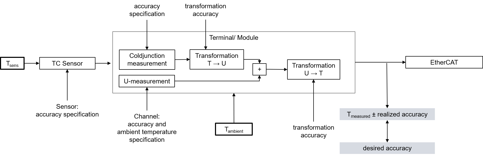
The thermocouple measurement consists of a chain of measuring and computing elements that affect the attainable measurement deviation:
The voltage specification is the key factor for the temperature measuring accuracy that can be achieved. It is applied to the possible thermocouple types.
On account of
- the strong non-linearity that exists with thermocouples, which suggests a meaningful use of a thermocouple in a limited temperature range (if possible),
- the influence of an internal cold junction that may be used,
- the possible use of an external cold junction whose specification is not known at this point, and
- the influence of the ambient temperature on the used evaluation unit during voltage and cold junction measurement (leads to a change of Tmeasured due to ∆Tambient)
no detailed temperature specification tables are given in this documentation, but a short table and a specification plot are given for each sensor type. These can be found in the technical data of the respective terminal in the chapter "Measurement thermocouples" (e.g. for EL3314 "Specification thermocouple type B").
Short table with the following information:
- used electrical measuring range of voltage measurement,
- entire technically usable measuring range supported by the device.
This is also the linearization range of the temperature transformation, usually the application range of the respective thermocouple specified in the standards.
Note: the electrical measuring range is designed to cover the entire linearization range. The entire temperature measuring range can therefore be used - the measuring range recommended by Beckhoff for this type.
It is a subset of the technically usable measuring range and covers the measuring range usually used in industry, in which a relatively low measurement uncertainty is still achieved.
Since thermocouples have a non-linear characteristic over the entire implemented measuring range - as described in the chapter "Basics on thermocouples" in the I/O Analog Manual - the specification of the measurement uncertainty over this entire range as the so-called basic accuracy would be unrealistic and even misleading. A much smaller uncertainty is achieved in the temperature range commonly used in industry. Nevertheless, it is of course possible to use the device outside of the "recommended measuring range" (but within the "technically usable measuring range") - the specified measurement uncertainty in the "recommended measuring range" at 23 °C and 55 °C ambient temperature, where the specification of the measurement uncertainty at 55 °C corresponds to the value for 23 °C ±32 °C (largest temperature difference in the "recommended measuring range": 55 °C - 23 °C = 32 °C).
Thus, the measurement uncertainty at other ambient temperatures in the recommended measuring range can be approximately interpolated or extrapolated. The values can also be taken from the specification plot.
Attention: When determining the temperature coefficient (Tk [K/Kamb]): the specified values do not necessarily have to be present at the same Tsens! To determine Tk, it is best to read the measurement uncertainty values from the plot at Tsens and calculate Tk.
 | Information on the sensor types in the short tables The values for the sensor types listed in the short tables are shown here merely for informative purposes as an orientation aid. All data are given without guarantee and must be cross-checked against the data sheet for the respective sensor employed. |
"Specification Plot":
A comprehensive specification statement as a graphical representation of the measurement uncertainty for Tsens in the entire technically usable measuring range at
- the two ambient temperatures mentioned and
- additionally at 39 °C ambient temperature.
The representation of the measurement uncertainty at 39 °C ambient temperature (mean temperature between 23 °C and 55 °C) shows the nonlinear influence of temperature on the measurement uncertainty.
If accuracy values outside of the "recommended measuring range" are required, they can thus be read graphically here.
Notes on the calculation of detailed specifications
If further specifications are of interest, they can or must be calculated from the values given in the voltage specification.
The sequence:
- General: The conversion is explained here only for one measuring point (a certain input signal); the steps simply have to be repeated in case of several measuring points (up to the entire measuring range).
- The determination of the entire temperature error at a measuring point results from two steps:
- Determination of the temperature error from the error of the voltage measurement,
- Determination of the error by the cold junction measurement at the temperature of the measuring point.
- Note: Due to the non-linearity of the thermocouples, it is not possible to easily add the temperature errors
- If the measured voltage is not known at the measured temperature measuring point, the measured value MW = UMeasuring point (TMeasuring point) must be determined with the help of an U→T table.
- The deviation is calculated at this voltage value:
- Via the total equation

- or a single value, e.g. ESingle = 15 ppmFSV
- the measurement uncertainty in [mV] must be calculated:
Evoltage(Umeasuring point) = ETotal(Umeasuring point) · FSV
or: Evoltage(Umeasuring point) = ESingle(Umeasuring point) · FSV
or (if already known) e.g.: Evoltage(Umeasuring point) = 0.003 mV - Also, for the calculation of the cold junction error required for further calculations, the entire error must be calculated using the above equation.
- The slope at the point used must then be determined:
ΔUproK(Tmeasuring point) = [U(Tmeasuring point + 1 °C) - U(Tmeasuring point )] / 1 °C
with the help of an U→T table - The cold junction error is given as a temperature in °C. The temperature error must then be converted into a voltage error in [mV] via the slope at the temperature measuring point:
ECJC, U(Tmeasuring point) = ECJC, T · ΔUproK(Tmeasuring point) - The combined error in [mV] must then be calculated using a square addition of the voltage error and the cold junction error:

- For calibrated thermocouples, the thermocouple error can also be included at this point in order to determine the combined error of the entire system in mV. For this purpose, all three error influences in [mV] (voltage, cold junction, thermocouple) must be added squarely.
- The temperature measurement uncertainty can be calculated via the voltage measurement uncertainty and the slope
ETemp(Umeasuring point) = (Evoltage+CJC(Tmeasuring point)) / (ΔUproK(Tmeasuring point))