Sample program for individual temperature calculation in the PLC
The terminals from the EL331x-xxxx series are used for the convenient measurement of temperatures with thermocouples. For this purpose they are equipped with various conversion tables for different types of thermocouples as well as an internal cold junction measurement. However, it is possible that a type of thermocouple might be used that is not stored in the firmware. In this case the EL331x offers the following method:
- Measure the thermocouple voltage at the terminal in the voltage mode of the EL331x
- Measure the temperature of the internal cold junction (CJ) in the terminal. This is offered in the CoE for each channel.
- Offset the two values in the controller/PLC in consideration of the desired linearization curve/table for the temperature at the place of measurement.
This calculation method, called cold junction compensation (CJC), corresponds approximately to that which is stored in the terminal for the implemented types.
The sample program implements such a procedure and produces a temperature value that takes into account the channel-wise cold junction temperature from the CoE. By way of example the terminal is continually switched between voltage and temperature measurement in the type K, thus enabling a comparison of the two temperature values. A recording of the measured values from channel 1 of the EL3314 on a type K thermocouple with the TwinCAT Scope is illustrated below (units 0.1 °C):
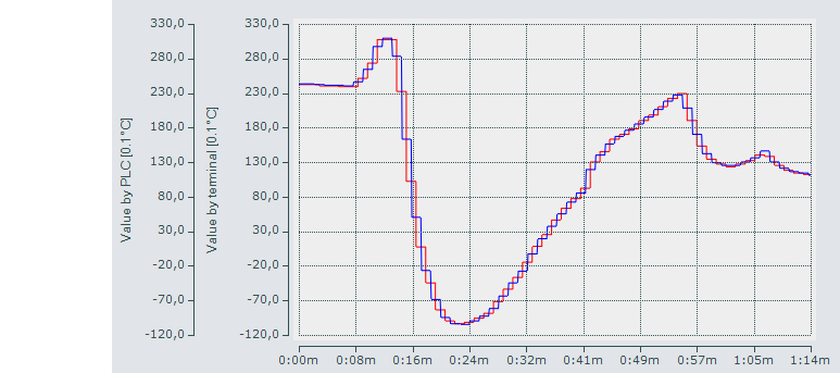 Fig.284: Blue: temperature values from the PLC calculation; red: PDO values in the temperature measurement range
Notes:
- the EL331x-xxxx also offers a third way of determining temperature - via an externally measured cold junction. See chapter "Operation with an external cold junction" in this documentation.
- The sample program operates with a sampling points table with 10 entries for a type K thermocouple. The values must be adjusted accordingly if a different thermocouple is used. The entries in the field variable "aTCElement" are to be made in µV and the temperature values from -30 °C to +60 °C allocated in 10° steps. The assignment of the value for "nBuffer_INT" in nState =14 in MAIN must also be adjusted (e.g. 5 for type N thermocouple).
- The sample program contains a variable "stUserNetId" in the function block "FB_COE_ACCESS" in which the AMS-Net-ID of the configuration to be used is to be entered. It is required among other things for reading the cold junction temperatures. If the terminal is not located in the first position after the coupler, then the entry for the variable "nUserSlaveAddr" must also be adjusted.
- After starting the program the terminal is set to the "NoCoEStorage" state so that the continuous CoE access for switching between the temperature and voltage measurement modes does not lead in the long run to damage to the terminal's internal EEPROM. This switching is not necessary if the EL331x only ever operates in voltage measurement mode in real use.
- Note that the EL331x-xxxx approximates the characteristic curve via a second-degree polynomial and thus produces more precise temperature values than the calculation by the sample program, which merely carries out a linear interpolation between the sampling points.
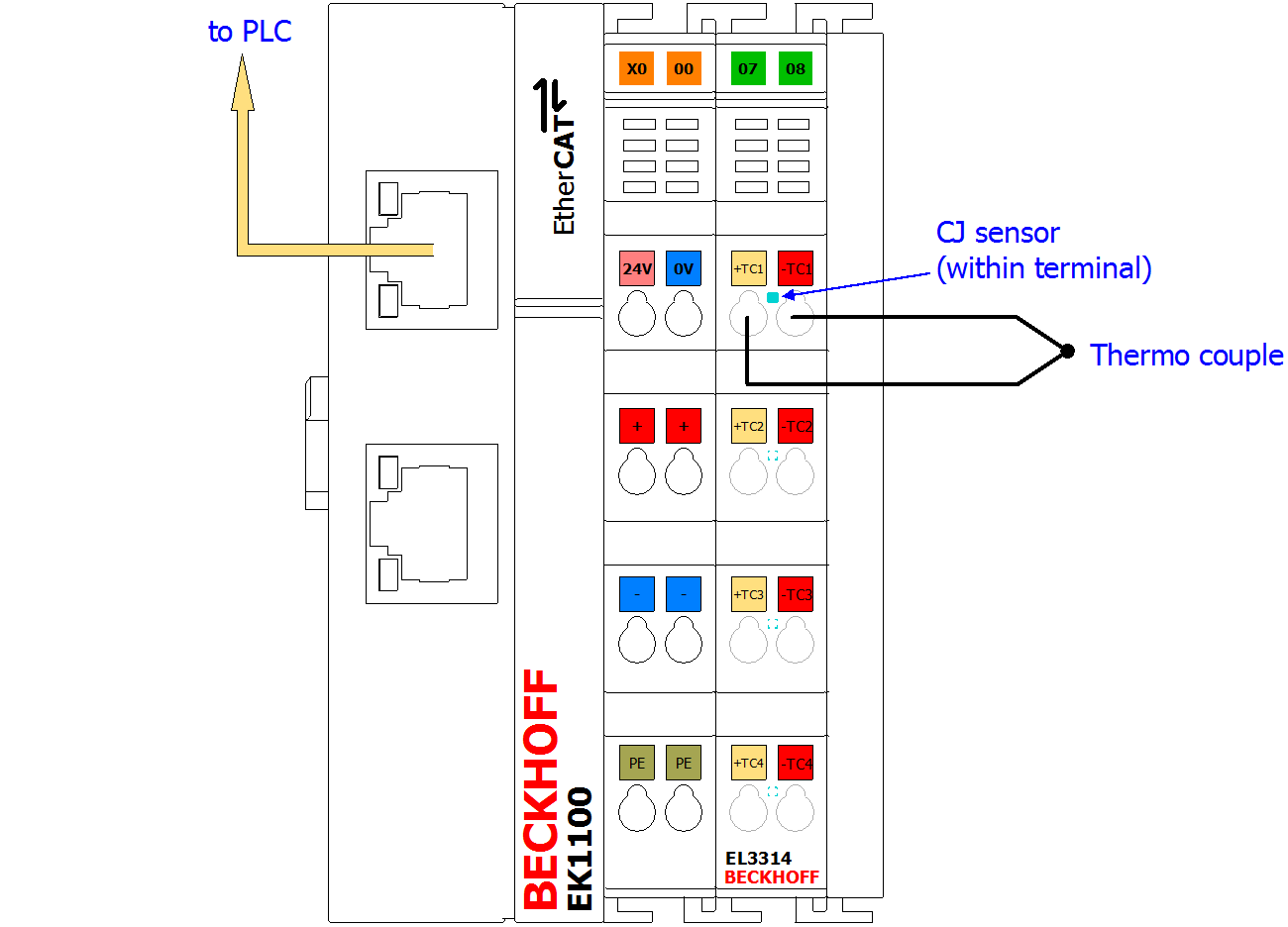 Fig.285: Structure of the sample program for "separate temperature calculation with CJC in the PLC"
Download: Program link
Preparations for starting the sample programs (tnzip file / TwinCAT 3)
- Click on the download button to save the Zip archive locally on your hard disk, then unzip the *.tnzip archive file in a temporary folder.
- Select the .tnzip file (sample program).
- A further selection window opens. Select the destination directory for storing the project.
- For a description of the general PLC commissioning procedure and starting the program please refer to the terminal documentation or the EtherCAT system documentation.
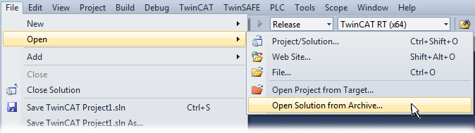 Fig.286: Opening the *. tnzip archive
Extract from the sample program:
Deklarationsteil:
// THIS CODE IS ONLY AN EXAMPLE - YOU HAVE TO CHECK APTITUDE FOR YOUR APPLICATION
PROGRAM MAIN
VAR

   nBuffer_INT           : INT;         // Buffer for reading or writing values from/to CoE objects
   aTCElement            : ARRAY[0..9] OF REAL := // Type K µV entries in 10°C Steps:
      [-1156, -778, -392, 0, 397, 798, 1203, 1612, 2023, 2436];
   nTabIndex             : INT;         // Index of node in table

   nT_start              : INT := -300; // -30°C for 0.1°C resolution
   nT_ResTab             : REAL := 100; //  10°C resultion of table (for 0.1°C resolution of values)

   // Variables for calculation:
   // ---------------------------
   nDiff_U_node2node     : REAL;    // Voltage difference of two nodes
   nDiff_U_node2U_TC     : REAL;    // Voltage difference of node and U TC
   nSlope                : REAL;    // Slope for 1st interpolation (temperature to voltage)
   nResidual             : REAL;    // Residual value for interpolation
   nRelation             : REAL;    // Relation for 2nd interpolation (voltage to temperature)
   // ===========================
   nU_TC                 : REAL;     // Voltage of temperature inkl. CJC
   nT_CJ                 : REAL;     // Cold junction temperature
   nU_CJ                 : REAL;     // Corresponding voltage of CJ
   nT_Result             : INT;      // Resulting Temperatur (resolution 0.1°C)
END_VAR
Ausführungsteil (nState=100):
// Cold junction temperature by CoE:
nT_CJ := INT_TO_REAL(nBuffer_INT);
// 1. Convert temperature to voltage:
// ========================================================================
// Determinate index of table:
nTabIndex := TRUNC_INT((nT_CJ - nT_start)/nT_ResTab);

// Calculate difference of two values with real value between them:
nDiff_U_node2node := (aTCElement[nTabIndex+1]-aTCElement[nTabIndex]);

// Get residual value of real value with integer value:
nResidual := nT_CJ - (nTabIndex * nT_ResTab + nT_start);

// Calculate slope nSlope = DY / DX:
nSlope := nDiff_U_node2node/nT_ResTab;

// Calculate interpolated voltage of the cold junction (m*x+b):
nU_CJ := nSlope * nResidual + aTCElement[nTabIndex];
// ========================================================================

// 2. Add this value to the PDO value:
nU_TC := INT_TO_REAL(nTC_Inputs_Value) + nU_CJ;
// ========================================================================

// 3. Convert calculated voltage to temperature:
// ========================================================================
//  Search index of higher target node:
nTabIndex := 0;
 // Loop as long U TC is greater than a node:
WHILE nU_TC > aTCElement[nTabIndex] DO
   nTabIndex := nTabIndex + 1;
END_WHILE
// Loop ended with resulting nTabIndex

IF nTabIndex = 0 THEN
   // Temperature is below first table entry: end here
   nT_Result := nT_start;
ELSE
   // Voltage difference between U_TC and lower target node
   nDiff_U_node2U_TC := nU_TC - aTCElement[nTabIndex-1];

   // Voltage difference between two target nodes with U_TC nested between them:
   nDiff_U_node2node := aTCElement[nTabIndex]-aTCElement[nTabIndex-1];

   // Relation of the two differencies:
   nRelation := nDiff_U_node2U_TC/nDiff_U_node2node;

   // Resulting temperature in 0.1°C resoltion:
   nT_Result := REAL_TO_INT(nT_start + (nRelation+nTabIndex-1) * nT_ResTab);
END_IF