Filter (conversion times)
The EL331x terminals are equipped with the following digital filters, cf. the data flow in chapter Data processing
- Filter 1: in ADC, "ADC filter"
- in all EL331x
- setting in CoE 0x80n0:15
- the higher the filter frequency, the faster the conversion time.
- always have notch filter behavior (average filter)
- the filter frequencies are set for all channels of the EL331x terminals centrally via index 0x8000:15 (channel 1). The corresponding higher channel indices 0x8010:15, 0x8020:15, 0x8030:15 etc. of the EL3312/EL3314/EL3318 have no function
- "Enable Filter" in CoE 0x80n0:06 has no function, the ADC filter is always active
- Filter 2: in firmware, “MC Filter (software filter in the microcontroller (MC)”
- Only for EL3314-0002, EL3314-0092, EL3314-0010/0020/0030
- Setting in CoE 0x80n0:1A: inactiv/IIR/FIR
Filter behavior
Example IIR low-pass 100 Hz:
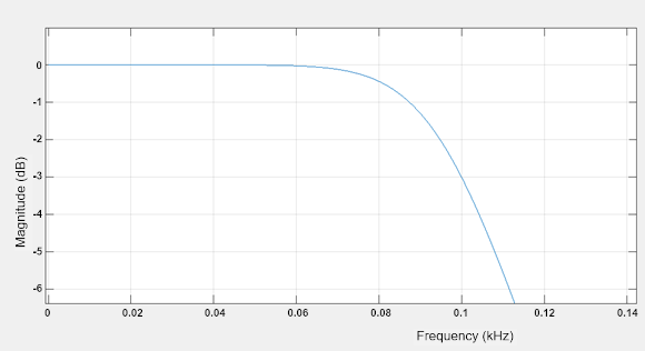 Fig.268: Example IIR low-pass 100Hz
The notch filters attenuate the designated frequency and multiples thereof, here using the example 50 Hz FIR,
Typical curve of a notch filter set to 50 Hz:
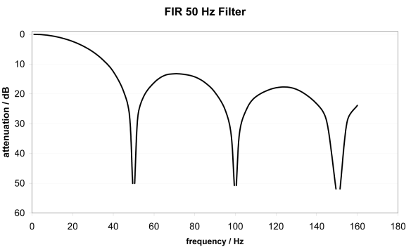 Fig.269: Example notch filter
Conversion time/update rate from filter 1 (ADC filter)
The conversion time is dependent on the following:
Active channels * Number of measurements * Filter period + Calculation time = Conversion time
Example: EL3311 (1 channel), 3 measurements (thermocouple, wire break, cold junction), filter 50 Hz
1 channel * 3 measurements * (1/50 Hz) + 3 ms ≈ 63 ms
Example: EL3314 (2 channels), 3 measurements (thermocouple, wire break, cold junction), filter 50 Hz
2 channels * 3 measurements * (1/50 Hz) + 6 ms ≈ 126 ms
Example: EL3314 (4 channels), 3 measurements (thermocouple, wire break, cold junction), filter 50 Hz
4 channels * 3 measurements * (1/50 Hz) + 12 ms ≈ 252 ms
Typical conversion times with 3 measurements (thermocouple, wire break, cold junction)
Conversion times in relation to the filter frequencies:
| Conversion time (update time) | ||||
|---|---|---|---|---|---|
Filter frequency | EL3311 | EL3312 | EL3314 | EL3314-0010 | EL3318 |
5 Hz | 0.6 s | 1.2 s | 2.4 s | 1.6 s | 3.5 s |
10 Hz | 0.3 s | 0.6 s | 1.2 s | 800 ms | 1.75 s |
50 Hz | 63 ms | 126 ms | 250 ms | 165 ms | 380 ms |
60 Hz | 53 ms | 106 ms | 210 ms | 145 ms | 320 ms |
100 Hz | 33 ms | 66 ms | 130 ms | 86 ms | 200 ms |
500 Hz | 9 ms | 18 ms | 33 ms | 26 ms | 70 ms |
1000 Hz | 6 ms | 12 ms | 24 ms | 18 ms | 50 ms |
2000 Hz | 5 ms | 10 ms | 20 ms (14 from FW10) | 14 ms | 40 ms |
3750 Hz | 4 ms | 8 ms | 19 ms (12 from FW10) | 12 ms | 35 ms |
7500 Hz | 4 ms | 7 ms | 19 ms (10 from FW10) | 12 ms | 30 ms |
15000 Hz | 3 ms | 7 ms | 19 ms (9 from FW10) | 12 ms | 30 ms |
30000 Hz | 3 ms | 7 ms | 19 ms (8 from FW10) | 12 ms | 30 ms |
mV range | 3 ms | 6 ms | 12 ms | 12 ms | 25 ms |
Conversion times in relation to the filter frequencies, EL3314-0002 (from FW02), EL3314-0092:
Filter frequency | EL3314-0002, EL3314-0092 |
|---|---|
50/60 Hz | 114 ms |
2.5 Hz | 2400 ms |
5 Hz | 1200 ms |
10 Hz | 600 ms |
16.6 Hz | 360 ms |
20 Hz | 300 ms |
50 Hz | 122 ms |
60 Hz | 102 ms |
100 Hz | 62 ms |
200 Hz | 31 ms |
400 Hz | 17 ms |
800 Hz | 10 ms |
1000 Hz | 8 ms |
2000 Hz | 5 ms |
4000 Hz | 4 ms |
mV range | 4 ms |
Conversion time from filter 2 (MC filter)
If available, the MC filter can further attenuate the temperature value. The final conversion rate results from the conversion time set in the ADC (table in previous section) and the MC setting according to
FFilter frequency final [Hz] = 1 / (k * tconversion time ADC)
with k as measure for the signal rise up to 70% (-3 dB) after
Filter designation | k | Behavior |
|---|---|---|
FIR4 | 3 | Notch filter behavior |
FIR8 | 6 | |
FIR16 | 12 | |
FIR32 | 23 | |
IIR0 | 2 | Low-pass behavior |
IIR1 | 5 | |
IIR2 | 10 | |
IIR3 | 19 |
Example: for the EL3314-0010 with ADC filter 50 Hz (thus 166 ms according to the above table) and FIR16 results in FFilter frequency final = 1 / (12 * 166 ms) = 0.5 Hz.