Connection
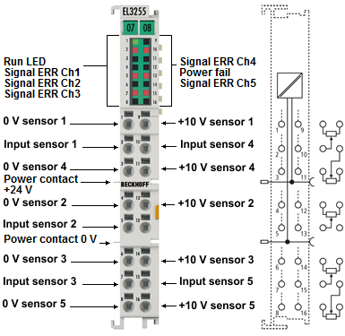 Fig.4: EL3255
The 24 V supply via the power contacts is required for the operation of the EL3255.
Terminal point | Description | |
|---|---|---|
Name | No. | |
0 V | 1 | Potentiometer 1, feed A*) |
Input 1 | 2 | Potentiometer 1, tap |
0 V | 3 | Potentiometer 4, feed A*) |
0 V | 4 | Potentiometer 2, feed A*) |
Input 2 | 5 | Potentiometer 2, tap |
0 V | 6 | Potentiometer 3, feed A*) |
Input 3 | 7 | Potentiometer 3, tap |
0 V | 8 | Potentiometer 5, feed A*) |
+10 V | 9 | Potentiometer 1, feed B**) |
Input 4 | 10 | Potentiometer 4, tap |
+10 V | 11 | Potentiometer 4, feed B**) |
+10 V | 12 | Potentiometer 2, feed B**) |
- | 13 |
|
+10 V | 14 | Potentiometer 3, feed B**) |
Input 5 | 15 | Potentiometer 5, tap |
+10 V | 16 | Potentiometer 5, feed B**) |
*) The 0 V terminals are directly connected to each other. 0 V is indirectly connected to "Power contact 0 V" for the purpose of potential definition (resistor several 100 Ohm), the connection is not current carrying!
**) The +10V connections are not connected to each other so that a short circuit etc. can be diagnosed on a channel-by-channel basis. A connection on the system side is not recommended.