Connection of analog RTD signal lines
The RTD input terminals of the EL32xx series measure the analog resistance of the sensor. The voltage drop at the sensor (depending on the connection technology incl. the supply line resistances) is equivalent to the sensor resistance and thus a measure for the temperature of the sensor if the sensor curve is known.
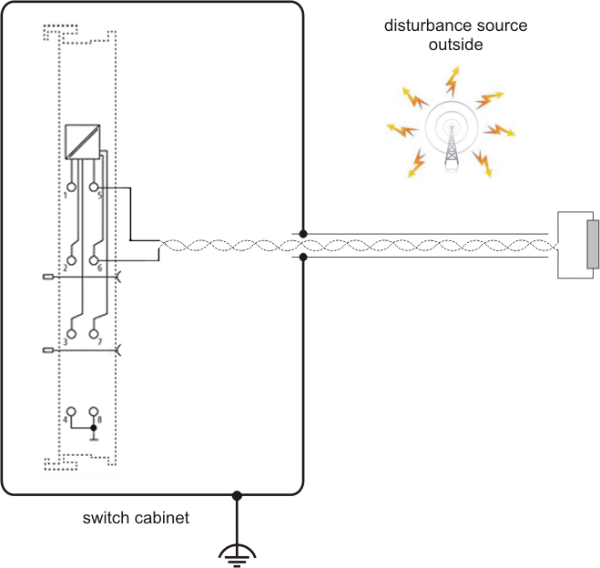
To ensure that the analog signals are measured as free of interference as possible, a procedure for connecting the analog signal lines is presented below.
Measures
- Sensor cable to be used
- Tightly twisted
- Shielded copper braid
- Use low-resistance cable, particularly for 2-wire connection
- Keep sensor and sensor cables free from external potential.
The GND connections (3/7 for EL3201, EL3202) must never be connected to other potentials. - The resistance for the RTD sensor (e.g. 100 or 1000 Ω nominal) should be chosen based on the ratio between sensor resistance and line resistance, taking account of the connection type (2/3/4-wire).
 | Shielding measures Due to the complexity in the "EMC" area, there is no generally applicable guideline, but only technical measures in accordance with the state of the art, which can sometimes contradict each other. These must be checked for feasibility and effectiveness, taking into account the plant specifications, and applied by the plant installer following assessment. The following notes on shielding are to be understood as technical suggestions that have proven themselves from time to time in practical use.
|
A shielding approach is described below that in many cases improves the measurement quality. The suggested measures must be checked for feasibility and effectiveness in the actual plant.
- Apply the shield with a low-resistance and enveloping the cable by 360°
- at the entry point into the control cabinet, the shield should be earthed conductively
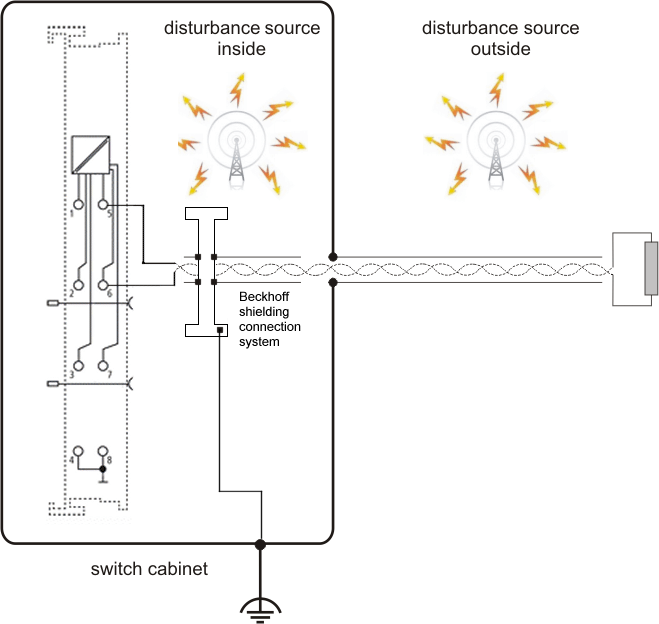
- the shield should be earthed again at the terminal
- at the terminal connection point, if present
- if no terminal connection point is available, ground the shield as close as possible to the terminal (see also Beckhoff shielding connection system).
- to avoid ground loops, the shield can be undone after entry in the control cabinet.
A capacitive connection to the terminal shield contact is possible. - avoid unshielded cable lengths of > 50 cm