Settings via the CoE directory
CoE online directory
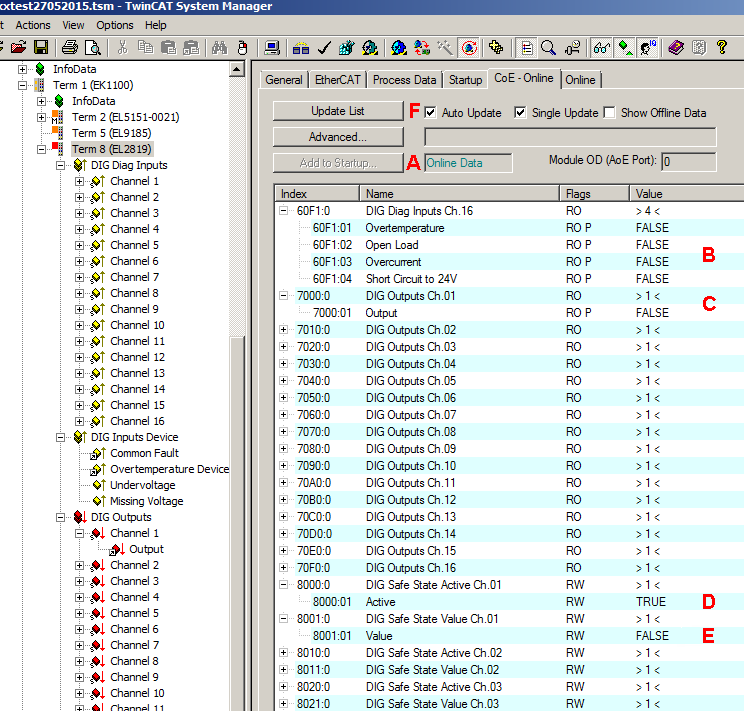 Fig.21: EL2819 CoE directory
The online data are accessible (A) if the terminal is online, i.e. connected to the EtherCAT Master TwinCAT and in an error-free RUN state (WorkingCounter = 0). The entries “DIG Safe State Active Ch.n (index 0x80n0) (D) and “DIG Safe State Value Ch.n” (index 0x80n1) (E) can be changed online; please also observe the Notes on the CoE interface and on the StartUp-List.
The diagnostic data of the channels can be read under “DIG Diag Inputs Ch.n” (index 0x60n1) (B).
The diagnostic data of the terminal can be read under “DIG Inputs Device” (index 0xF600).
The state of the outputs can be read under “DIG Outputs Ch.n” (index 0x70n0) (C).
The display in TwinCAT is continuously updated if (F) has been activated.
DIG Safe State Active (index 0x80n0:01) / DIG Safe State Value (index 0x80n1:01)
The setting in “DIG Safe State Active” (index 0x80n0:01) defines whether the outputs should assume a safe state in the case of a bus error. The safe state of the output in the case of a bus error is defined with “DIG Safe State Value” (index 0x80n1:01).
- “DIG Safe State Active“ = TRUE and
- “DIG Safe State Value“ = TRUE: the output is switched on.
- “DIG Safe State Active“ = TRUE and
- “DIG Safe State Value“ = FALSE: the output is switched off
- “DIG Safe State Active“ = FALSE
- The state of the output is retained. Entries in “DIG Safe State Value” (index 0x80n1:01) have no effect.
Flow-chart illustration of the sequence in case of a bus error
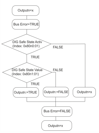 Fig.22: Change of state of the outputs in the case of a bus error
Tabular example:
DIG Safe State Active | DIG Safe State Value | Output before bus error | Output during bus error | Output after bus error |
|---|---|---|---|---|
TRUE | TRUE | FALSE | TRUE | FALSE |
TRUE | TRUE | TRUE | ||
TRUE | FALSE | FALSE | FALSE | FALSE |
TRUE | FALSE | TRUE | ||
FALSE | FALSE / TRUE | FALSE | FALSE | FALSE |
TRUE | TRUE | TRUE |
Graphical example:
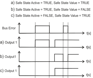 Fig.23: Graphical illustration of the channel state during a bus error