Process data
Parameterization
An EL2819 is parameterized via 2 tabs in the TwinCAT System Manager: the Process Data tab (A) for the communication-specific settings and the CoE directory (B) for the settings in the slave.
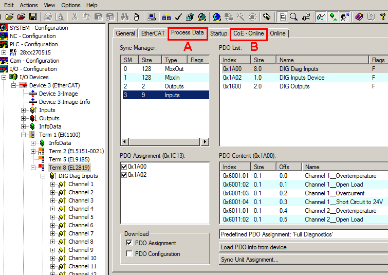 Fig.18: EL2819 “Process Data” tab
- Changes to the process data-specific settings are generally only effective after a restart of the EtherCAT master:
Restart TwinCAT in RUN or CONFIG mode; RELOAD in CONFIG mode - Changes to the online CoE directory
- are in general immediately effective
- are generally stored in non-volatile memory in the terminal/slave. They should be entered in the CoE StartUp list so that the settings are accepted after a replacement of the terminal. The CoE StartUp list is processed at each EtherCAT start and the settings are loaded into the slave.
Illustration of the process data and structural contents
The EL2819 provides three different process data for transmission:
- the diagnostics per channel “DIG Diag Inputs” (64-bit),
- the device diagnostics “DIG Inputs Device” (4-bit),
- The switching state of the outputs “DIG output” (16-bit)
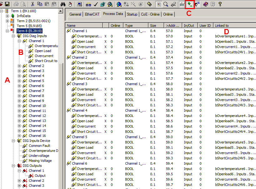 Fig.19: EL2819 Online illustration of the process data and structural contents in the System Manager
The plain text display of the bit meanings is particularly helpful not only in commissioning but also for linking to the PLC program.
By right-clicking on the Status variable in the configuration tree (A), the structure can be opened for linking (B).
Activation of the “Show Sub Variables” button (C) displays all subvariables and links to the PLC (D) in the online view.
“Predefined PDO Assignment” selection dialog (from TwinCAT 2.11 build 1544 onwards)
The process data to be transmitted (PDO, ProcessDataObjects) can be selected by the user
- for all TwinCAT versions via the “Predefined PDO Assignment” selection dialog (see fig. “EL2819 Process Data tab” A) or
- selectively for individual PDOs (see fig. “EL2819 Process Data tab” B)
These changes become effective after activation and an EtherCAT restart or a reload.
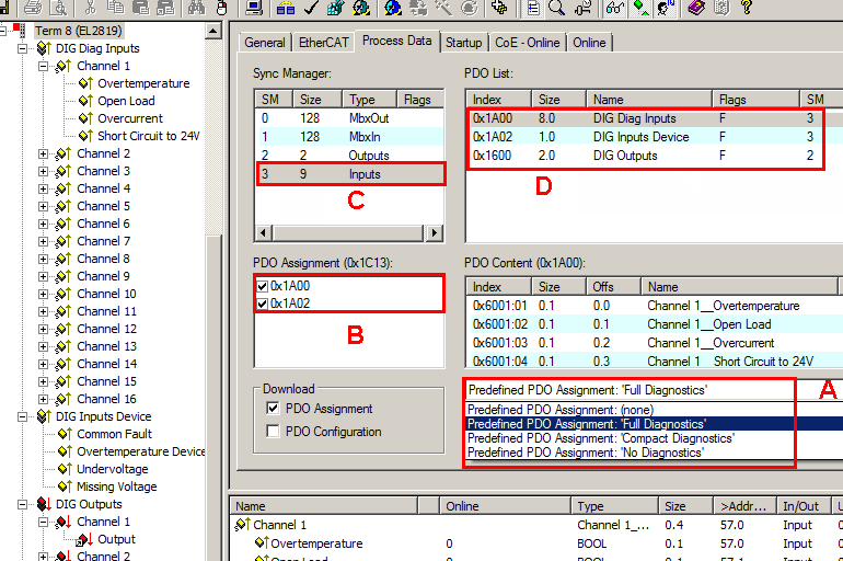 Fig.20: EL2819 “Process Data” tab
A | Selection of the diagnostic scope via the selection dialog “Predefined PDO Assignment” |
B | Display of (optional) PDOs (process data objects) |
C | Selection of the required Sync Manager |
D | Display of the PDOs available for selection |
Three pre-defined PDO assignments can be selected:
- Full Diagnostics:
Inputs: Selection of the PDOs 0x1A00 (diagnostics per channel) and 0x1A02 (device diagnostics). Both the diagnostic data for each channel and the data for the device diagnostics are displayed and transmitted.
Outputs: PDO 0x1600 (switching state of the outputs) is displayed and transmitted. - Compact Diagnostics:
Inputs: Selection of the PDO 0x1A02 (device diagnostics). Only the diagnostic data for the device are displayed in the System Manager and transmitted to the control system.
Outputs: PDO 0x1600 (switching state of the outputs) is displayed and transmitted. - No Diagnostics: Neither 0x1A00 nor 0x1A02 is selected. No diagnostic data are displayed in the System Manager and none are transmitted to the control system.
Outputs: PDO 0x1600 (switching state of the outputs) is displayed and transmitted.
 | Compact Diagnostics, No Diagnostics When converting from “Full Diagnostics” to “Compact Diagnostics” or “No Diagnostics”, or when deactivating the PDO 0x1600, links already established to the deactivated objects are deleted. |