Overload protection
 | Technical data Please note the information in the technical data regarding load type, max. output current and short circuit current. |
When switching on lamp loads, high starting currents occur that are limited by the output circuit of the terminals (see fig. Overload current limitation).
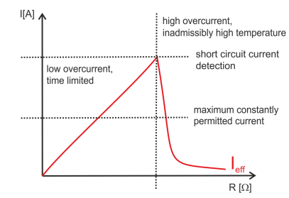
In case of a long-term overload and/or short-circuit, the output is protected by the thermal switch-off of the channel.
The output circuit of the terminal limits the current. The terminal maintains this current until important self-heating of the channel occurs.
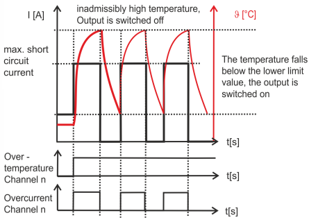
On exceeding the upper temperature limit, the terminal switches the channel off.
The channel is switched on again after it has cooled down to below the lower temperature limit.
The output signal is clocked until the output is switched off by the controller or the short-circuit is eliminated (see fig. Schematic illustration of the thermal switch-off in case of overload). The clock frequency depends on the ambient temperature and the load of the other terminal channels.
Short-circuit or prolonged overload on a channel leads to an increase in the device temperature. If several channels are overloaded, this leads to a rapid increase in the device temperature. The overloaded channels are switched off when the upper limit for the device temperature is exceeded. The channels are only switched on again if the temperature falls below the lower limit values for both the device and the channel. The non-overloaded channels continue operating properly.
When switching off inductive loads, high induction voltages result from interrupting the current too quickly. These are limited by an integrated free-wheeling diode (switch-off energy [inductive] see Technical data). Since the current reduces only slowly, a delayed switch-off can occur in many control applications. For example, a valve remains open for many milliseconds. Switch-off times are realized that correspond, for instance, to the switch-on time of the coil.
| Protection against high induction voltages To protect against voltage peaks such as can occur when switching inductive loads, we recommend to provide suitable protective circuits (e.g. with the free-wheeling diode, RC combination or varistor) directly at the actuator. |
