Sample program 3 - combination of input and output triggers

Program description and function
As already described in the chapter Using the trigger output with the trigger input the trigger output of the EL2596-xxxx can be used as a response to the trigger input.
In this sample program, a signal is generated at the input trigger with an EL2202. The EL2202 is a digital output terminal with a switch-on time of <1 µs. This terminal is used because a steep edge is then applied to the trigger input of the EL2596. In the sample program, a visualization can then be used to specify which trigger mode (described in the table in the chapter Activating the trigger output) is to be used. In addition, all LED-specific parameters, such as output current, etc. and all time-specific parameters, such as the delay at the LED and/or trigger output, can be specified.
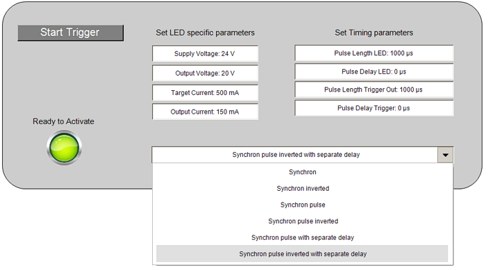 Fig.251: Sample program 2 - Visualization
All characteristic values for the LED and trigger outputs are specified via the visualization. When starting the trigger output via the “Start Trigger” button in the visualization, all specified values are transferred to the CoE and the process data. A pulsating signal is then started at the output of the EL2202. With each rising edge at the trigger input of the EL2202, a pulse with the specified length is output at the LED or trigger output. If new parameters are to be set, the output of the EL2202 must be stopped manually via the “Stop Trigger” button. Then the parameters can be adjusted via the visualization. When the trigger output is restarted, all parameters are transferred to the CoE and the process data.
An EL2202 digital output terminal 24 V and an EL2596 1-channel LED strobe control terminal are required in order to use the sample. The trigger output can be measured with an oscilloscope, for example. The wiring of the hardware for the sample program is shown in the following figure.
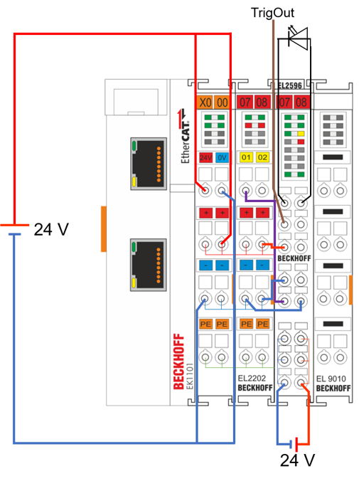 Fig.252: Sample program 2 - Hardware wiring