EL2596-0010
EL2596-0010 - connection
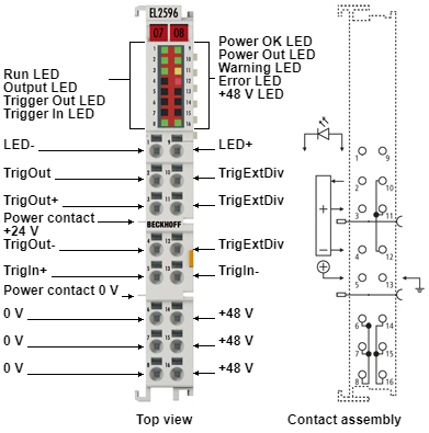 Fig.7: EL2596-0010 - connection
 Terminal point | No. | Comment |
|---|---|---|
LED- | 1 | - Output for the LED |
TrigOut | 2 | Trigger output signal |
TrigOut+ | 3 | Connection for the + voltage supply for the trigger output |
TrigOut- | 4 | Connection for the - voltage supply for the trigger output |
TrigIn+ | 5 | + Trigger input |
LED supply GND | 6 | Ground (GND) of the input voltage (no supply via power contacts), internally connected to pins 7 and 8 |
LED supply GND | 7 | Ground (GND) of the input voltage (no supply via power contacts), internally connected to pins 6 and 8 |
LED supply GND | 8 | Ground (GND) of the input voltage (no supply via power contacts), internally connected to pins 6 and 7 |
LED+ | 9 | + Output for the LED |
TrigExtDiv | 10 | Connection option for a voltage divider for adjusting the output voltage for the trigger output, internally connected to pins 11 and 12 |
TrigExtDiv | 11 | Connection option for a voltage divider for adjusting the output voltage for the trigger output, internally connected to pins 10 and 12 |
TrigExtDiv | 12 | Connection option for a voltage divider for adjusting the output voltage for the trigger output, internally connected to pins 10 and 11 |
TrigIn- | 13 | - Trigger input |
LED supply +48 V | 14 | 48 V input voltage (no supply via power contacts), internally connected to pins 15 and 16 |
LED supply +48 V | 15 | 48 V input voltage (no supply via power contacts), internally connected to pins 14 and 16 |
LED supply +48 V | 16 | 48 V input voltage (no supply via power contacts), internally connected to pins 14 and 15 |
EL2596-0010 - LEDs
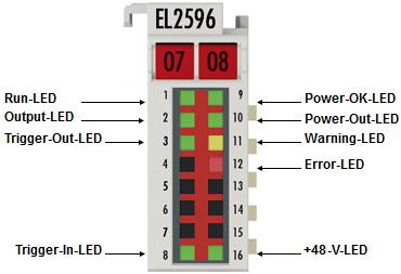 Fig.8: EL2596-0010 - LEDs
 LED | Color | Meaning | |
|---|---|---|---|
RUN | green | This LED indicates the terminal's operating state: | |
off | State of the EtherCAT State Machine: INIT = initialization of the terminal | ||
flashing | State of the EtherCAT State Machine: PREOP = function for mailbox communication and different default settings set | ||
Single flash | State of the EtherCAT State Machine: SAFEOP = verification of the sync manager channels and the distributed clocks. | ||
on | State of the EtherCAT State Machine: OP = normal operating state; mailbox and process data communication is possible | ||
flickering | State of the EtherCAT State Machine: BOOTSTRAP = function for terminal firmware updates | ||
OUTPUT | green | The LED output is active. | |
TRIGGER OUT | green | The trigger output is active. | |
TRIGGER IN | green | The trigger input is wired and active. | |
POWER OK | green | The input voltage is within the configured range. | |
POWER OUT | green | The LED drive circuit is ready to operate. | |
WARNING | yellow | off | no defect |
on |
| ||
ERROR | red | off | no defect |
on |
| ||
+48 V | green | Input voltage is within the specified range | |