Normal digital output
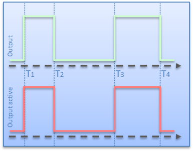 Fig.139: Normal digital output
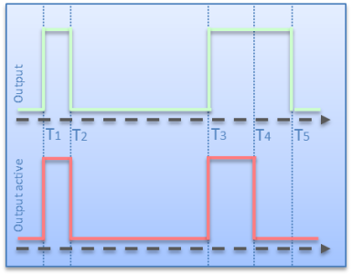 Fig.140: Digital output with specification of the pulse length
In the case of the "normal digital output", the input signal "Output" is switched directly through to the driver stage and returned as feedback in "Output active" (see fig. Normal digital output).
T1 and T3 thereby represent the switch-on times and T2 and T4 the switch-off times.
The temporal behavior with "Impulse length" additionally activated is shown in fig. Digital output with preset pulse length:
- T1 and T3 are the switch-on times
- T4 - T3 is the "Impulse length"
- T2 - T1 has a shortened duty cycle due to the premature resetting of "Output"
- The resetting of "Output" at time T5 has no effect on the output, since the output time has already expired