LEDs and connection
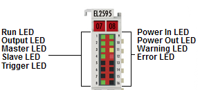 Fig.24: EL2595 LEDs
LEDs
LED | Color | Meaning | |
|---|---|---|---|
RUN | green | This LED indicates the terminal's operating state: | |
off | State of the EtherCAT State Machine: INIT = initialization of the terminal | ||
flashing | State of the EtherCAT State Machine: PREOP = function for mailbox communication and different default settings set | ||
Single flash | State of the EtherCAT State Machine: SAFEOP = verification of the sync manager channels and the distributed clocks. | ||
on | State of the EtherCAT State Machine: OP = normal operating state; mailbox and process data communication is possible | ||
flickering | State of the EtherCAT State Machine: BOOTSTRAP = function for terminal firmware updates | ||
OUTPUT | green | off | Output is disabled or EL2595 is not ready to operate |
on | Output is enabled and EL2595 is ready to operate | ||
MASTER | green | Output stage is configured as master mode (slave mode is not supported in the current firmware) | |
SLAVE | green | reserved | |
TRIGGER | green | Trigger input is triggered externally | |
POWER IN | green | off | Input voltage is outside the configured range |
on | Input voltage is inside the configured range | ||
POWER OUT | green | off | Output voltage is outside the configured range |
on | Output voltage is inside the configured range | ||
WARNING | yellow | off | no defect |
on | - Supply voltage is outside the configured range | ||
DEV ERROR | red | off | no defect |
on | Configuration error, e.g.: - no supply voltage connected | ||
EL2595 pin assignment
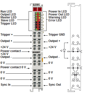 Fig.5: EL2595 pin assignment
Terminal point | No. | Comment |
|---|---|---|
Trigger + | 1 | Trigger input + () |
Output + | 2 | Output + for load |
+24 V | 3 | 24 V control voltage (internally connected to positive power contact) |
Output - | 4 | Output - for load |
0 V | 5 | 0 V control voltage (internally connected to negative power contact) |
0 V | 6 | 0 V control voltage (internally connected to negative power contact) |
0 V | 7 | 0 V control voltage (internally connected to negative power contact) |
Sync In | 8 | reserved, connection may not be used |
Trigger GND | 9 | Trigger input - (must be connected to GND of the same potential of Trigger +) |
Output + | 10 | Output + for load |
+24 V | 11 | 24 V control voltage (internally connected to positive power contact) |
Output - | 12 | Output - for load |
0 V | 13 | 0 V control voltage (internally connected to negative power contact) |
0 V | 14 | 0 V control voltage (internally connected to negative power contact) |
0 V | 15 | 0 V control voltage (internally connected to negative power contact) |
Sync Out | 16 | reserved, connection may not be used |