Extended mode
For high update rates and animations, the extended process image can be used. These data must be added in the tab "Process data" per channel (Outputs - 0x16n1).
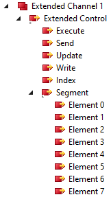 Fig.137: EL2574 - Process data display in TwinCAT tree "Extended Channel 1
Here, the LEDs are divided into segments of eight LEDs, named as elements. For each of the eight LEDs 4 bytes of output data are available. Thus, the color and brightness of each LED can be specified. Each Byte corresponds to a color component with the sequence red, green, blue, white (0xWWBBGGRR).
Due to the fact that eight LEDs always correspond to one segment and the numbering starts at 0, the first LED of a segment results by:
Index * 8.
Subsequently, the individual LEDs can be defined via the eight elements in the segment. Thus, eight LEDs can be rewritten in the pixel buffer per cycle.
Procedure
The following procedure is required to specify the data and change the connected pixels:
- 1. Presetting the segment number via "Index
- 2. Specification of the setpoints for the eight LEDs in the selected segment via the eight available elements
- 3. Writing the data into the pixel buffer via “Write” bit toggling the "Execute" bit.
- 4. If necessary, repeat steps 1 and 2 until all required segments are completely prepared.
- 5. Update the data from the pixel buffer into the frame buffer by setting the "Update" bit to 1
- 6. Toggling the "Execute" bit to execute the update
- 7. Transfer data:
- If the object 0x80p0:02 Enable Cyclic Frame Output is enabled in the CoE, the data from the frame buffer is automatically transferred to the connected LEDs.
- Alternatively, sending can be triggered manually by setting the "Send" bit to 1.
- 8. Toggle the "Execute" bit to execute the transmission.
- 9. The changes on the connected LEDs are visible.
The transfer to the buffers or between the buffers and to the strip can also be triggered in one cycle. For this purpose, the desired commands "Write", "Update" and "Send" must be set to 1. The commands are triggered by toggling the "Execute" bit.
Notice | |
Loss of data possible Note the status of the Busy and Transmit bits before transmitting new data.
|