Updating procedure
The terminal has different buffers internally.
The data from the PLC is written into the first buffer (pixel buffer) in order to build the "image" for connected LEDs. The data is sent from the PLC either via a Command or a Write command together with an Execute.
From this buffer the finished data is written to the next buffer (frame buffer). For this purpose, the update command is used with an execute. In order to finally send the data out of this buffer to the LEDs, a Send command must be executed with the Execute. This process is shown graphically below.
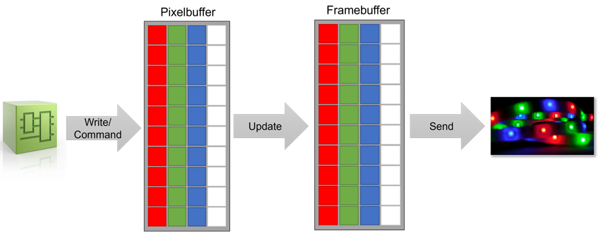 Fig.125: Buffer sequence
For the timings to transfer data from the PLC to the connected LEDs different times have to be considered.
PLC to pixel buffer (Write/Command)
The duration for the transfer of data from the PLC to the pixel buffer depends on the selected operation mode (Command, Extended) and the set cycle time.
All four channels can be written in parallel from the PLC, so that no addition of times is necessary.
- Command mode
In the command process image, one command can be sent per cycle. So it depends on the number of commands. If all pixels are to be written with one color, it is possible here to write all data in one cycle. - Extended mode
One segment can be written per cycle in the extended process image. A segment comprises 8 individual pixels.
Example:
To write to 512 pixels, 64 cycles are required until everything has been written. With a cycle time of 500 µs it takes 32 ms to write the data from the PLC into the first buffer.
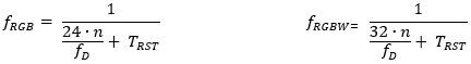
Frame buffer to LEDs (Send)
The duration for the transfer of data between the buffers depends on whether RGB or RGBW LEDs are used. For this purpose, the following calculation can be used with the data sheet values for the LED type used.
n: Number of LEDs to be manipulated | |
|
|
Frame rate: | |
The update of the data to the terminal and the sending to the strip can run in parallel, because two different buffers in the terminal are accessed.
In addition, all four channels can always be processed in parallel.