LEDs and connection
EL2564-0010 - connection
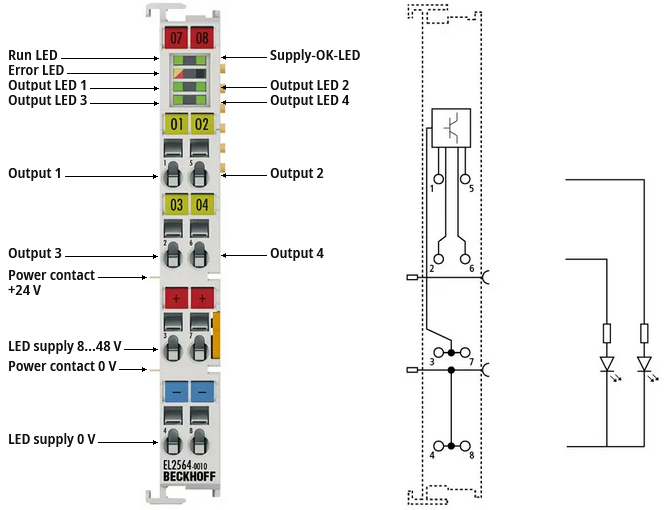
Terminal point | No. | Comment |
|---|---|---|
Output 1 | 1 | PWM output 1 |
Output 3 | 2 | PWM output 3 |
LED supply 8…48 V | 3 | 8...48 V supply voltage for the LEDs |
LED supply 0 V | 4 | Ground of the LED supply voltage |
Output 2 | 5 | PWM output 2 |
Output 4 | 6 | PWM output 4 |
LED supply 8…48 V | 7 | 8...48 V supply voltage for the LEDs |
LED supply 0 V | 8 | Ground of the LED supply voltage |
Notice | ||
 | Observe notes on mounting and connection Observe the information in the chapter "Mounting and wiring" and the notes on the connection! | |
EL2564-0010 - LEDs
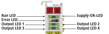
LED | Color | Meaning | |
|---|---|---|---|
RUN | green | This LED indicates the terminal's operating state: | |
off | State of the EtherCAT State Machine: INIT = initialization of the terminal | ||
flashing | State of the EtherCAT State Machine: PREOP = function for mailbox communication and different default settings set | ||
single flash | State of the EtherCAT State Machine: SAFEOP = verification of the Sync Manager channels and the distributed clocks. | ||
on | State of the EtherCAT State Machine: OP = normal operating state; mailbox and process data communication is possible | ||
flickering | State of the EtherCAT State Machine: BOOTSTRAP = function for Firmware updates of the terminal | ||
Supply-OK | green | The LED supply voltage is within the permissible range. | |
ERROR | yellow | Warning | |
red | Error | ||
OUTPUT 1…4 | green | The LED output is active. | |