Principles of fiber-optic technology
When using fiber-optic cables for the transmission of data, there are various factors that influence the signal transmission and have to be observed in order to guarantee reliable transmission. Important principles of fiber-optic technology are described below.
Attenuation
Less light reaches the end of a connection with fiber-optic cables than is input at the start of the connection. This loss of light between the start and end of the transmission link is called attenuation. The attenuation between two points is often stated in decibels (dB). However, the decibel is not a unit, but a ratio – in the case of a fiber-optic cable it is the ratio of the light energy at the start of the connection to that at the end. It is one tenth of a Bel (B) (1 B = 10 dB). In general, decibel indicates a power level LP from the ratio of one power P1 to another power P2.
- LP[dB] = 10*log10(P1/P2)
A positive power factor is a signal amplification, a negative power factor conversely a weakening or attenuation of the signal.
The attenuation of a fiber-optic connection is essentially determined by three influencing factors. These influencing factors are the attenuation in the fiber-optic, the attenuation in the connector and the attenuations that result from the splices in the fiber-optic connection. The total attenuation is therefore given by
- Fiber-optic link attenuation [dB] = fiber loss attenuation [dB] + connector insertion attenuation [dB] + splice insertion attenuation [dB]
Where
- fiber loss attenuation [dB] = fiber attenuation coefficient [dB/km)] x length [km]
- connector insertion attenuation [dB] = number of connectors x connector insertion attenuation [dB]
- splice insertion attenuation [dB] = number of splices x splice insertion attenuation [dB]
Dispersion
A further influence that needs to be observed with the signal transmission is the dispersion. Dispersion describes the spreading or widening of a light pulse. Due to propagation differences resulting in the fiber-optic cable from different injection angles of the light waves, the optical pulse widens and is therefore wider at the output than at the input. The longer the transmission link, the greater the dispersion.
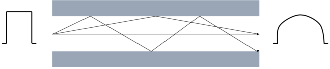
If higher data rates are to be transmitted by the fiber-optic cable, the pulses must be sent faster at the input. What may happen then, however, is that pulses at the output run into one another and can no longer be distinguished from one another. The dispersion thus limits the maximum bandwidth of the fiber-optic connection.
The maximum bandwidth is specified in the data sheet for a fiber-optic cable as the bandwidth/length ratio in the unit MHz*km. Therefore, the longer a transmission link, the smaller the available bandwidth. The bandwidth/length ratio or product is always specified in the data sheet for a fiber-optic cable. The length of the transmission link can then be calculated with the necessary bandwidth.
s [km] = bandwidth [MHz] / bandwidth/length ratio [MHz/km]
Further influences on the signal transmission
In addition to the main influences (attenuation and dispersion) that limit the transmission link, care must be taken when installing and maintaining fiber-optic transmission links.
Sharp kinks and micro-bends in the fiber-optic lead to additional reflections in the fiber, as a result of which the influences of the attenuation and dispersion are increased. The specified bending radii of fiber-optic cables must be adhered to.
Poorly installed connectors also have a great influence on the signal quality. In case of poor connections, the fiber-optic may be too far away from the connecting piece, so that the light waves do not enter the fiber at the right angle of entry.
The third influence on the signal transmission that needs to be observed is soiling of, or damage to the ends of optical fibers. Due to the size of the fibers, often just 125 µm, dirt or damage cannot be discerned with the naked eye. Only a microscope with a sufficient magnification (at least factor 100) enables the fiber ends to be checked. To prevent soiling, the cable cap supplied with the cable should always be fitted to the fiber end.
Power and attenuation budget
The power budget specifies the minimum power present between transmitter and receiver. The attenuation budget, conversely, describes the attenuation present between transmitter and receiver due to the three attenuation influences - fiber, connectors and splices - described above.
Transceivers (from the words transmitter and receiver) are installed in fiber-optic transmitters and/or receivers. This transceiver is a combined transmitting and receiving device. The data sheet for the transceiver contains two values that are necessary for the calculation of the power budget. These values are the minimum output power of the transmitter and the maximum sensitivity of the receiver. Therefore, the worst case, i.e. the lowest power between transmitter and receiver, is always considered. Both values are often specified in the unit decibel milliwatt (dBm). dBm describes a power level in relation to a reference value of 1 mW.
- LP[dB] = 10*log10(P1/1 mW)
0 dBm then corresponds to a power value of 1 mW, positive dBm values indicate power values >1 mW and negative dBm values indicate power values <1 mW.
The difference between the maximum output power and the minimum sensitivity at the input results in the power level.
- Power level = minimum output power - maximum sensitivity
The attenuation level results from the influences on the attenuation described above.
- Attenuation level [dB] = fiber loss attenuation [dB] + connector insertion attenuation [dB] + splice insertion attenuation [dB]
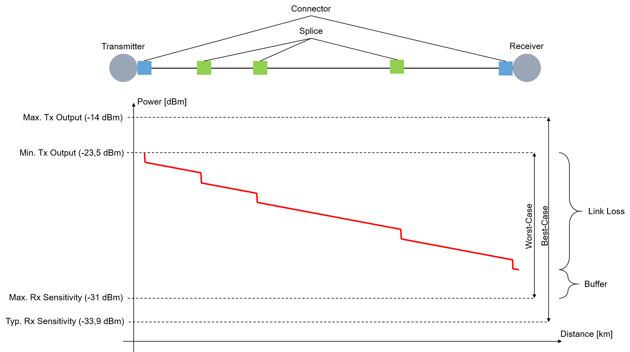
The attenuation level must not exceed the power level. A power buffer of >3 dB is recommended so that long-term operation is possible over many years despite power losses. Sources located in the transmitter can age and lose power, connectors or splices can deteriorate, or connectors can become dirty if they are opened for diverting or testing. If cables are inadvertently cut through, excess play is required in order to accommodate splices for reconnecting.
Evaluation of a fiber-optic transmission link by means of measurement
A fiber-optic transmission link can be described and evaluated with parameters from data sheets. In order to obtain a real result for the attenuation over the entire link, however, the link must be measured using an optical power meter (OPM). The power at the end of the transmission link can be measured with an OPM.
When measuring with an OPM, it is essential to ensure that only the required adapter (FC, SC, …) is screwed to the OPM. If several adapters are screwed above one another to the OPM, the distance between the connector and the detector in the OPM is too large, with the result that lower power values are displayed (greater attenuation than actually exists).
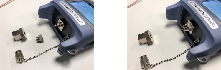
OPM without adapter | OPM with FC adapter screwed on |
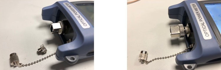
OPM with SC adapter screwed on | OPM with FC and SC adapter screwed on - WRONG |