Example program #2: Parameterization of the CycleCounter and watchdog behavior
 | Using the sample programs This document contains sample applications of our products for certain areas of application. The application notes provided here are based on typical features of our products and only serve as examples. The notes contained in this document explicitly do not refer to specific applications. The customer is therefore responsible for assessing and deciding whether the product is suitable for a particular application. We accept no responsibility for the completeness and correctness of the source code contained in this document. We reserve the right to modify the content of this document at any time and accept no responsibility for errors and missing information. |
Example 2: Parameterization of the CycleCounter and watchdog behavior
 Download (sample file)
This example uses a TwinCAT 3 PLC program to demonstrate the behavior of an EL2262 with regard to the CycleCounter and Watchdog cases.
The example is also applicable to the EL1262-0010.
Data:
- 2 ms cycle time
- 10x oversampling on both channels
- defined output pattern, which is repeated every 4 cycles
In the Settings dialog of the terminal the SyncManager watchdog time is set to 25 ms.
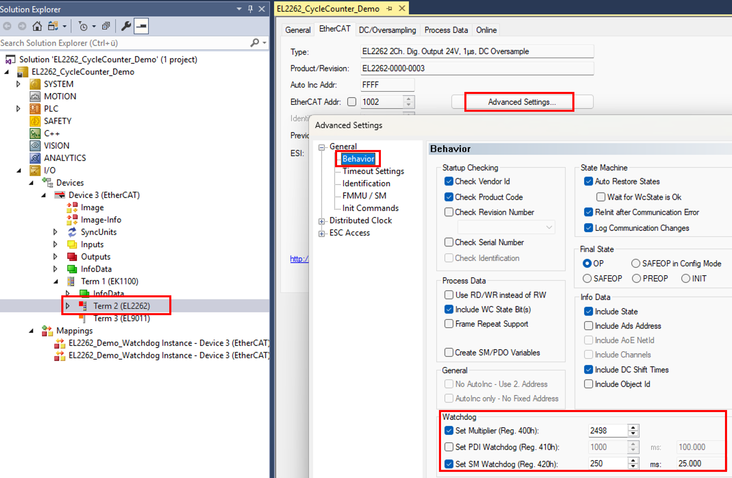 Fig.184: System Manager Watchdog Time
After starting the PLC, the CycleCounter and the Watchdog behavior for each channel can be set online:
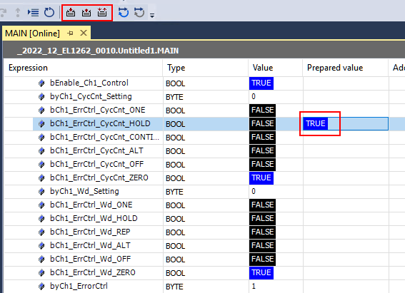
It is loaded every second via ADS/acyclic data traffic into the registers 0x0F00/0x0F01 and is then effective.
Any PDI errors counted in register 0x030D are read.
To readjust the communication interruption the EtherCAT cable can be pulled to the EL2262 or via DisableEcFrameSending the cyclic data sending can be stopped by software.
| Using the ESC registers If settings are loaded into ESC registers (in this case 0x0F00, for example), they are retained until they are overwritten or until the system is de-energized. If the system was de-energized, the required values have to be re-loaded into the registers. |