Explanation of the output behavior in case of error (Watchdog, CycleCounter)
Behavior in case of error - Watchdog and CycleCounter
This output terminal depends on regular supply of cycle updated data from the controller. If this is not the case, two phases are to be distinguished and the following tools take effect
- Short absence (one cycle and more) → CycleCounter monitoring
In CycleCounter monitoring, the device wants to be assigned cyclically incremented values (+1) from the controller in the CycleCounter process data variables. Thus, it can determine whether a frame repetition or a LostFrame has occurred based on the consecutive values. If CycleCounter monitoring is not activated, the firmware is unable to detect the non-arrival of data and repeats the data of the last sample until the watchdog has run out. - Diagnosis: If no increment +1 is detected by the device, at least the internal register 030Dhex "PDI-Error" counts up by 1. A counter overflow 255 → 0 is not interpreted as an error. If the counter increment is greater than 1 once and subsequently 1 again, only one PDI error is output, since all the counter values after the event have an increment of 1. This register can be read out acyclically, e.g. by the PLC, see "Explanations on CycleCounter monitoring".
- Output behavior: Furthermore, in this case the firmware continues to use the output according to the ESC register setting:
- for channel 1: Register 0x0F00
Bit 0 = TRUE → Parameterization is activated
Bit 1 to 3: Default value for behavior at CycleCounterError, see below. - for channel 2: Register 0x0F01
Bit 0 = TRUE → Parameterization is activated
Bit 1 to 3: Default value for behavior at CycleCounterError, see below. - Note: The two byte registers 0x0F00 and 0x0F01 should be written simultaneously as 1 word access.
- Possible register values for the CycleCounter behavior are (names are taken from the demo program below):
ZERO: "000": A logical zero "0" is output (default)
ONE: "001": A logical one "1" is output
HOLD: "010": The value of the last bit in the previous cycle is output
CONTINUE: "011": A PDI error is output, but the data currently in the buffer is output. This can also be outdated data.
ALT: "100": zero and one are output alternately
OFF: "101" (EL2262 only): the output stage is switched to high-resistance. No signal level is driven.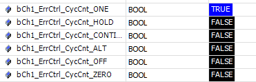
Figure from TC3 sample program - Prolonged absence (watchdog time and longer) → SM-Watchdog
The device has a parameterizable SM-Watchdog (SyncManager watchdog) as output terminal. In each successful EtherCAT cycle this is 'wound up' again or reset. If it is not used for a certain time (default: 100 ms), the outputs are set to a definable state. For the time-based parameterization of the SM watchdog, see here. - The output behavior after the watchdog has been triggered is parameterized via the ESC registers as follows:
- For channel 1: Register 0x0F00
Bit 0 = TRUE → Parameterization is activated
Bit 4 to 6: Default value for watchdog behavior, see below. - Channel 2: Register 0x0F01
Bit 0 = TRUE → Parameterization is activated
Bit 4 to 6: Default value for watchdog behavior, see below. - The default behavior for watchdog monitoring is output=FALSE
- Note: the two byte registers 0x0F00 and 0x0F01 must be written as 1 word access at the same time The default values for the watchdog behavior are:
- Possible register values for the watchdog behavior are (names are taken from the demo program below):
ZERO: " "000": A logical zero is output (default)
ONE: "001": A logical one is output
HOLD: "010": The value of the last bit in the previous cycle is output
REP: "011": The data of the last cycle is output repeatedly
ALT: "100": Zero and one are output alternately
OFF: "101" (EL2262 only): The output stage is switched to high-resistance. No signal level is driven
Since CycleCounter and Watchdog behavior are controlled by the same register, the two registers are to be described completely in 1 operation, see sample program.
 | Using the ESC registers If settings are loaded into ESC registers (in this case 0x0F00, for example), they are retained until they are overwritten or until the system is de-energized. If the system was de-energized, the required values have to be re-loaded into the registers. |
The following example about the terminal function in case of a communication interruption illustrates the resulting 3 phases.
- Invented signals (as specified by the PLC) are output on channel 1 and 2 of a EL2262 and observed with an oscilloscope.
- For demonstration purposes, channel 1 and 2 are parameterized differently
- The example also applies to the EL1262-0010 (outputs).
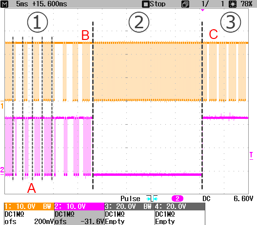 Fig.168: Example: error in EL2262 from FW09
- Phase 1: normal operation: cyclic process data are sent to the terminal in time, the terminal outputs the data.
In this example, channel 1 and 2 output the same signal curve, 10x oversampling, cycle time 2 ms, with a repeating pattern - general output = TRUE, 1 sample = FALSE
- general output = TRUE, 2 samples = FALSE, in the next cycle then
- general output = TRUE, 3 samples = FALSE, in the next cycle then
- generally output = TRUE, 4 samples = FALSE, then starting again.
In addition, the CycleCounterVariables are used. The data come from the sample program for watchdog parameterization. - Phase 2: CycleCounter monitoring: the terminal does not receive any new process data, the CycleCounter is no longer operated from the terminal's point of view.
This can occur for a short time (1 cycle) due to delayed data delivery or over a longer period due to communication interruption.
The watchdog is also no longer used because the SyncManager events do not occur and starts to expire, but has no effect yet.
The output behavior can be changed as above, in this example - channel 1 alternately outputs 0/1 during this phase
- channel 2 alternately outputs 0 during this phase
- Phase 3, watchdog case: the watchdog has expired after the parameterized time, in this example 25 ms.
The outputs now go into the parameterized or safe state.
The output behavior can be changed as below, in this example - channel 1 continuously outputs the last sample during this phase
- channel 2 outputs 1 during this phase
Note on the EL2262:
Firmware | CycleCounter monitoring behavior | Watchdog behavior |
|---|---|---|
< FW09 | Register 030Dhex: incremented + 1 | Outputs: FALSE |
>= FW09 | Register 030Dhex: incremented + 1 | Output behavior as parameterized |
CycleCounter monitoring demonstration
In this further example the watchdog is set to 25 ms. By default, the last sample block is output repeatedly in phase 2 until phase 3:
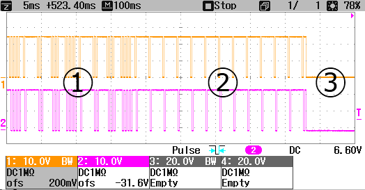 Fig.169: Default output behavior if CycleCounter monitoring is deactivated
If CycleCounter monitoring is activated, the default is output = FALSE in phase 2.
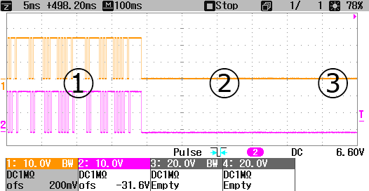 Fig.170: Default output behavior if CycleCounter monitoring is activated
Now the CycleCounter special behavior "ALT" in phase 2 is parameterized for channel 1 and the Watchdog special behavior "REP" for channel 2: :
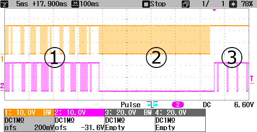 Fig.171: Parameterized output behavior (system-specific)