LEDs and connection
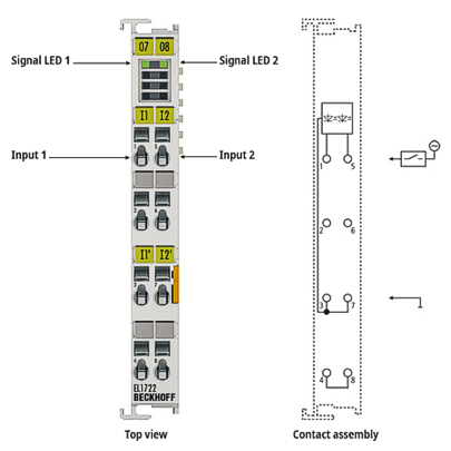 Fig.16: EL1722
| |
Risk of electric shock! Bring the Bus Terminal system into a safe, de-energized state before starting installation, disassembly or wiring of the terminal modules! |

EL1722 - LEDs | |||
|---|---|---|---|
LED | Color | Meaning | |
INPUT 1 | green | off | Signal voltage "0" (0 V ... 40 V) |
on | Signal voltage "1" (79 V ... 260 V) | ||
EL1722– connection | ||
|---|---|---|
Terminal point | Description | |
Designation | No. | |
Input 1 | 1 | Input 1 |
n.c. | 2 | not connected |
N | 3 | Neutral conductor for input 1 (internally connected to terminal point 7) |
n.c. | 4 | not connected (bridged with terminal point 8) |
Input 2 | 5 | Input 2 |
n.c. | 6 | not connected |
N | 7 | Neutral conductor for input 2 (internally connected to terminal point 3) |
n.c. | 8 | not connected (bridged with terminal point 4) |