LEDs and connection
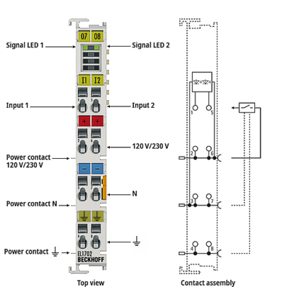 Fig.4: EL1702
| |
Risk of electric shock! Bring the Bus Terminal system into a safe, de-energized state before starting installation, removal or wiring of the terminal modules! |

Notice | |
Risk of device damage! Note that the use of potential separation terminals (e.g. EL9080) is necessary when planning the Bus Terminal system with different potentials on the power contacts (e.g., 24 VDC and 230 VAC)! |
EL1702 - LEDs | |||
|---|---|---|---|
LED | Color | Meaning | |
INPUT 1 | green | off | Signal voltage "0" (0 V ... 40 V) |
on | Signal voltage "1" (79 V ... 260 V) | ||
EL1702 - Connection | ||
|---|---|---|
Terminal point | Description | |
Name | No. | |
Input 1 | 1 | Input 1 |
120/230 V | 2 | Sensor supply for input 1 (internally connected to terminal point 6 and power contact 120/230 V) |
N | 3 | Ground for input 1 (internally connected to terminal point 7 and power contact “N”) |
⏚ | 4 | Earthing (internally connected to terminal point 8 and power contact ⏚) |
Input 2 | 5 | Input 2 |
120/230 V | 6 | Sensor supply for input 2 (internally connected to terminal point 2 and power contact 120/230 V) |
N | 7 | Ground for input 2 (internally connected to terminal point 3 and power contact “N”) |
⏚ | 8 | Earthing (internally connected to terminal point 4 and power contact ⏚) |