Configuration/ electrical settings
The first step is to make the electrical setting in CoE 0x80n0:01 for each channel according to the intended use (channel 1: n=0, channel 2: n=1).
Each channel can operate in either 5 V single-ended or RS mode.
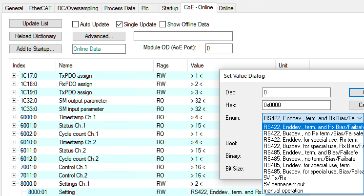 Fig.189: Setting "CoE- Online" tab, RS or single-ended operation
1. RS422/RS485 operation mode: the RS422/485 driver is electrically active on this channel. Termination resistor and bias resistors (also called: failsafe) are switchable per channel. Four common configurations can be selected here. It should be noted that RS422/485 is a differential signal between Tx+/Tx- or Rx+/Rx-. In general, operation with "Enddev., term. and Rx Bias/Failsafe" is successful with short cable lengths and only one remote terminal. Checking the electrical signal quality (crosstalk, rise times) by means of a suitable measuring instrument (e.g. oscilloscope) is recommended.
- RS422: bidirectional operation, input and output can be used independently of each other
- RS485: unidirectional operation e.g. for serial communication, input and output are internally already connected
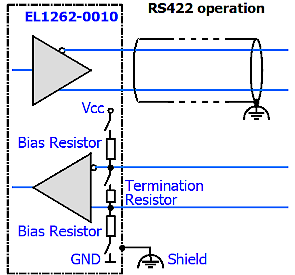 Fig.190: RS422: bidirectional operation
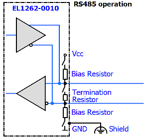 Fig.191: RS485: unidirectional operation
2. Operation mode "5 V Tx/Rx": the 5 V input/output is electrically active on this channel.
3. Operation mode "5 V permanent out": useful for test purposes or for supplying a remote terminal. A "5 V Tx/Rx" operation is then not possible.
If the 5 V output is to be used permanently for device supply simultaneously with RS operation, this must be set via "manual operation".
4. Operation mode "manual operation": if selected, the individual functions of the terminal can be enabled individually via 0x80n1
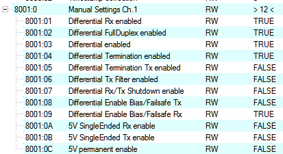 Fig.192: Activation of functions in CoE object 8001 in operation mode "manual operation"