LEDs and connection
EL1262
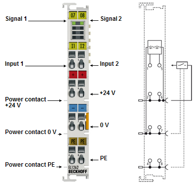 Fig.5: EL1262
EL1262 LEDs
LED | Color | Meaning | |
|---|---|---|---|
INPUT 1 - 2 | green | off | There is no input signal at the respective input |
on | +24 V input signal at the respective input | ||
EL1262 connection
Terminal point | Description | |
|---|---|---|
Name | No. | |
Input 1 | 1 | Input 1 |
+24 V | 2 | +24 V (internally connected to terminal point 6 and positive power contact) |
0 V | 3 | 0 V (internally connected to terminal point 7 and negative power contact) |
⏚ | 4 | Ground (internally connected to terminal point 8 and ⏚ power contact) |
Input 2 | 5 | Input 2 |
+24 V | 6 | +24 V (internally connected to terminal point 2 and positive power contact) |
0 V | 7 | 0 V (internally connected to terminal point 3 and negative power contact) |
⏚ | 8 | Ground (internally connected to terminal point 4 and ⏚ power contact) |
EL1262-0050
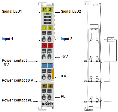 Fig.6: EL1262-0050
Notice | |
Be sure the correct supply voltage is used! The EL1262-0050 can only be operated with a 5 V supply voltage! The terminal will not work in a terminal network with a 24 V supply voltage at the power contacts! If necessary, use a EL9505 power supply terminal for supplying the EL1262-0050. |
EL1262-0050 LEDs
LED | Color | Meaning | |
|---|---|---|---|
INPUT 1 - 2 | green | off | There is no input signal at the respective input |
on | +5 V input signal at the respective input | ||
EL1262-0050 connection
Terminal point | Description | |
|---|---|---|
Name | No. | |
Input 1 | 1 | Input 1 |
+5 V | 2 | +5 V (internally connected to terminal point 6 and positive power contact) |
0 V | 3 | 0 V (internally connected to terminal point 7 and negative power contact) |
⏚ | 4 | Ground (internally connected to terminal point 8 and ⏚ power contact) |
Input 2 | 5 | Input 2 |
+5 V | 6 | +5 V (internally connected to terminal point 2 and positive power contact) |
0 V | 7 | 0 V (internally connected to terminal point 3 and negative power contact) |
⏚ | 8 | Ground (internally connected to terminal point 4 and ⏚ power contact) |
EL1264
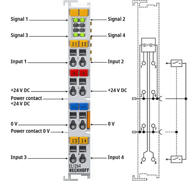 Fig.7: EL1264
EL1264 LEDs
LED | Color | Meaning | |
|---|---|---|---|
INPUT 1-4 | green | off | There is no input signal at the respective input |
on | +24 V input signal at the respective input | ||
EL1264 connection
Terminal point | Description | |
|---|---|---|
Name | No. | |
Input 1 | 1 | Input 1 |
+24 V | 2 | +24 V (internally connected to terminal point 6 and positive power contact) |
0 V | 3 | 0 V (internally connected to terminal point 7 and negative power contact) |
Input 3 | 4 | Input 3 |
Input 2 | 5 | Input 2 |
+24 V | 6 | +24 V (internally connected to terminal point 2 and positive power contact) |
0 V | 7 | 0 V (internally connected to terminal point 3 and negative power contact) |
Input 4 | 8 | Input 4 |