Example programs
 | Using the sample programs This document contains sample applications of our products for certain areas of application. The application notes provided here are based on typical features of our products and only serve as examples. The notes contained in this document explicitly do not refer to specific applications. The customer is therefore responsible for assessing and deciding whether the product is suitable for a particular application. We accept no responsibility for the completeness and correctness of the source code contained in this document. We reserve the right to modify the content of this document at any time and accept no responsibility for errors and missing information. |
Example 1: Frequency measurement with inductive sensor
 Download: (Example program)
Data:
- 1 ms cycle time
- 1000x oversampling on both channels
Connection diagram:
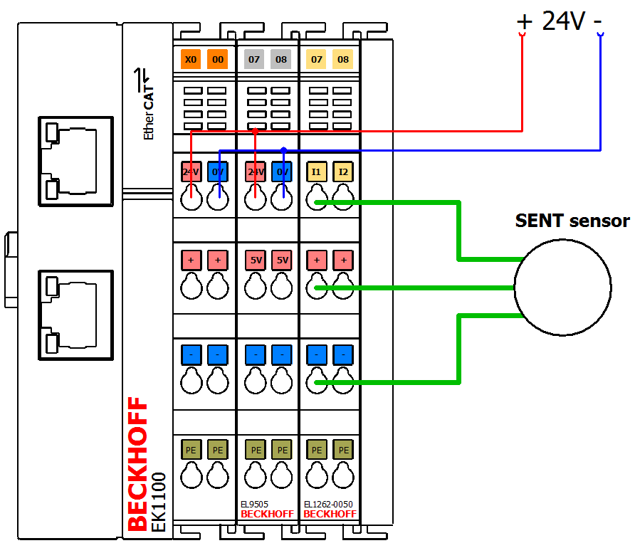
Example 2: Reading the SENT protocol
Download TwinCAT 2: (Example program)Download TwinCAT 3: (Example program)
- Hardware requirements:
- EL1262-0050
- EL9505
- A control that allows at least 1 ms task cycle time (IPC/ CX)
The EL1262 is able to work with an oversampling of 1 µs and also 1000 Bit per 1 ms are available.
A Sent telegram has a resolution of 3 µs per digit. So, if 1 µ resolution will be used, it is enough to interpret the received data signal.
Connection diagram:
Starting the example program
The application examples have been tested with a test configuration and are described accordingly.
Certain deviations when setting up actual applications are possible.
The following hardware and software were used for the test configuration:
- TwinCAT master PC with Windows XP Professional SP 3, TwinCAT version 2.10 (Build 1330) and INTEL PRO/100 VE Ethernet adapter
- Beckhoff EtherCAT Coupler EK1100, EL1262 and EL9011 Terminals
- Inductive proximity limit switch, switching to positive potential, with 3-wire connection, max. switching frequency: 3000 Hz
Procedure for starting the program
- After clicking the Download button, save the zip file locally on your hard disk, and unzip the *.TSM (configuration) and the *.PRO (PLC program) files into a temporary working folder
- Run the *.TSM file and the *.PRO file; the TwinCAT System Manager and TwinCAT PLC will open
- Connect the hardware in accordance with Wiring for example program 1 (other electrical or mechanical switching elements configured for a normally open function can be used instead of the inductive proximity limit switch), and connect the Ethernet adapter of your PC to the EtherCAT coupler (you will find further instructions on this in the corresponding coupler manuals)
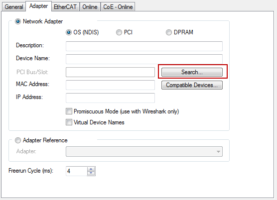
- Select the local Ethernet adapter (with real-time driver, if applicable) under System configuration, I/O configuration, I/O devices, Device (EtherCAT); then on the “Adapter” tab choose “Search...”, select the appropriate adapter and confirm (see Fig. Searching the Ethernet adapter + Selection and confirmation of the Ethernet adapter).
Activate and confirm the configuration (Fig. Activation of the configuration + Confirming the activation of the configuration)
- Confirm new variable mapping, restart in RUN mode (Fig. Generate variable mapping + Restarting TwinCAT in RUN mode)
Generating variable mapping 
Restarting TwinCAT in RUN mode - In TwinCAT PLC, under the “Project” menu, select “Rebuild all” to compile the project (Fig. Compile project)
Compile project - In TwinCAT PLC: log in with the “F11” button, confirm loading the program (Fig. Confirming program start), run the program with the “F5” button
Example 3: reading and writing TEDS data
Program description / function
This sample program illustrates how to read/write the data of a separate TEDS module (TEDS = Transducer Electronic Data Sheet). Such TEDS modules are available on the market for retrofitting sensors or actuators, in order to identify the device after installation or to read out specific data (calibration, manufacturer etc.). The device used in this example was an HBM TEDS 1−TEDS−BOARD−L, version 2018.
This sample program is expressly intended as a feasibility demonstration. Specifically, there is no claim to interoperability with any other TEDS modules. It is the responsibility of users to transfer the methods formulated here to their own implementations.
This demonstration does not cover TEDS modules that are integrated in the sensor and communicate on the sensor lines. This is common for IEPE (vibration) or strain gauges/measuring bridges. It is possible to connect an IEPE sensor equipped with TEDS to Beckhoff ELM3602/ELM3604 terminals.
The following configuration is required:
[EK1100] + [EL2262] + [EL9505] + [EL1262-0050] + EL9011
The configuration can control 2 TEDS modules. Only single-channel operation is shown in the example.
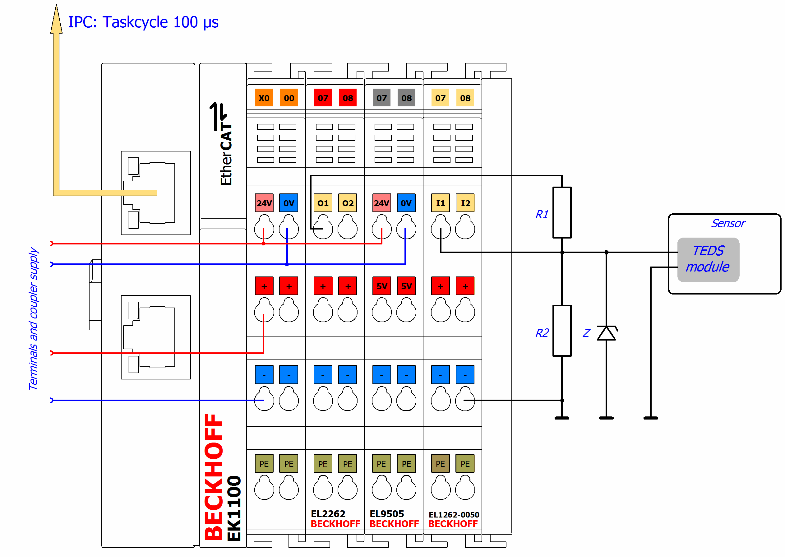
The voltage divider can be dimensioned with R1 = 2180 Ω (e.g. 680 Ω + 1500 Ω), R2 = 680 Ω and Z = 5,1 V for example.
Notes on the program (visualization)
First the URN has to be read (A). Only then are further functions available.
The program determines the URN for each bit by reinitializing the module, since the terminal for the input causes a time offset that is too large (see "Bit repeat count" at the top right).
Data can be written either by entering hexadecimal values (B) or a text string (ASCII) (C); hexadecimal values must be separated by spaces in the text field. Which of the two inputs is to be used for writing can be specified with the checkbox “Write ASCII data” (E):
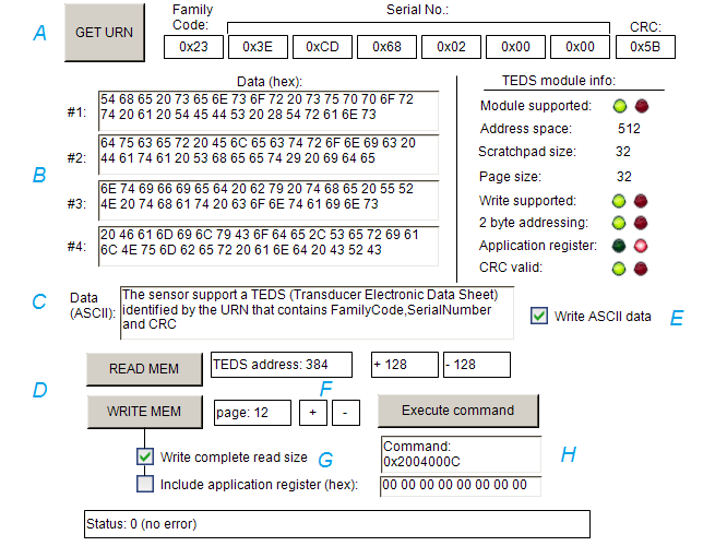
The basic function after the identified URN is (D) reading (READ MEM) and writing (WRITE MEM) TEDS data. By issuing such a command, the associated command statement is generated in the text field (H) and can also be changed and then executed with "Execute command". Via +/- the TEDS address or page can be changed (F). Both the start address and "page" can be entered directly for read / write accesses.
The hexadecimal data (B) of text field #1 to #4 each represent 32 bytes of the total read/write buffer size of 128 bytes, as configured in the sample program. If the checkbox “Complete read size” (G) is unchecked, only text field #1 will be used for writing usually (except the module supports page sizes > 32 byte). Accordingly, only the first characters of the ASCII data text will be written. In any case, the number of bytes as a page of the TEDS module is configured will be used. Note, that the module usually supports write access to addresses of a multiple value of the page size only. For example, assuming a page size of 32 bytes and the address 234 is input, an error 0x35 ‘writing fail’ will occur by a WRITE MEM command; but if address 352 is used, this is valid and there is no error).
Selection of “Include application register” provides whether the application register shall be written or read additionally (G).
Download:
Program
See information about the TEDS feature of the ELM3xxx in section “ELM Features/ TEDS”.
Preparations for starting the sample programs (tnzip file / TwinCAT 3)
- Click on the download button to save the Zip archive locally on your hard disk, then unzip the *.tnzip archive file in a temporary folder.
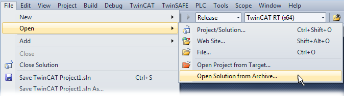
Opening the *. tnzip archive - Select the .tnzip file (sample program).
- A further selection window opens. Select the destination directory for storing the project.
- For a description of the general PLC commissioning procedure and starting the program please refer to the terminal documentation or the EtherCAT system documentation.
- The EtherCAT device of the example should usually be declared your present system. After selection of the EtherCAT device in the “Solutionexplorer” select the “Adapter” tab and click on “Search...”:
Search of the existing HW configuration for the EtherCAT configuration of the example - Checking NetId: the “EtherCAT” tab of the EtherCAT device shows the configured NetId:
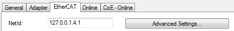 .
.
The first 4 numbers have to be identical with the project NetId of the target system. The project NetId can be viewed within the TwinCAT environment above, where a pull down menu can be opened to choose a target system (by clicking right in the text field). The number blocks are placed in brackets there next to each computer name of a target system. - Modify the NetId: By right clicking on “EtherCAT device” within the solution explorer a context menu opens where “Change NetId...” have to be selected. The first four numbers of the NetId of the target computer have to be entered; the both last values are 4.1 usually.
Example: - NetId of project: myComputer (123.45.67.89.1.1)
- Entry via „Change NetId...“: 123.45.67.89.4.1