Example program for EL1258 (EL1259): MT Visualization (TC 3)
This sample program uses a TwinCAT3 visualization to illustrate the multi-timestamp functionality of a digital input of the EL1258 (and accordingly EL1259). In 10x multi-timestamp and asynchronous (buffered) mode, one terminal input is controlled by a digital EL2002 output terminal. The sample program contains the EtherCAT configuration and the corresponding links to the PDOs of the terminals and uses channel 1 (the channel input must be connected to channel output accordingly).
The following structure is recommended for commissioning the sample program:
[EK1100] + [EL1258] + [EL2002] + [EL9011]
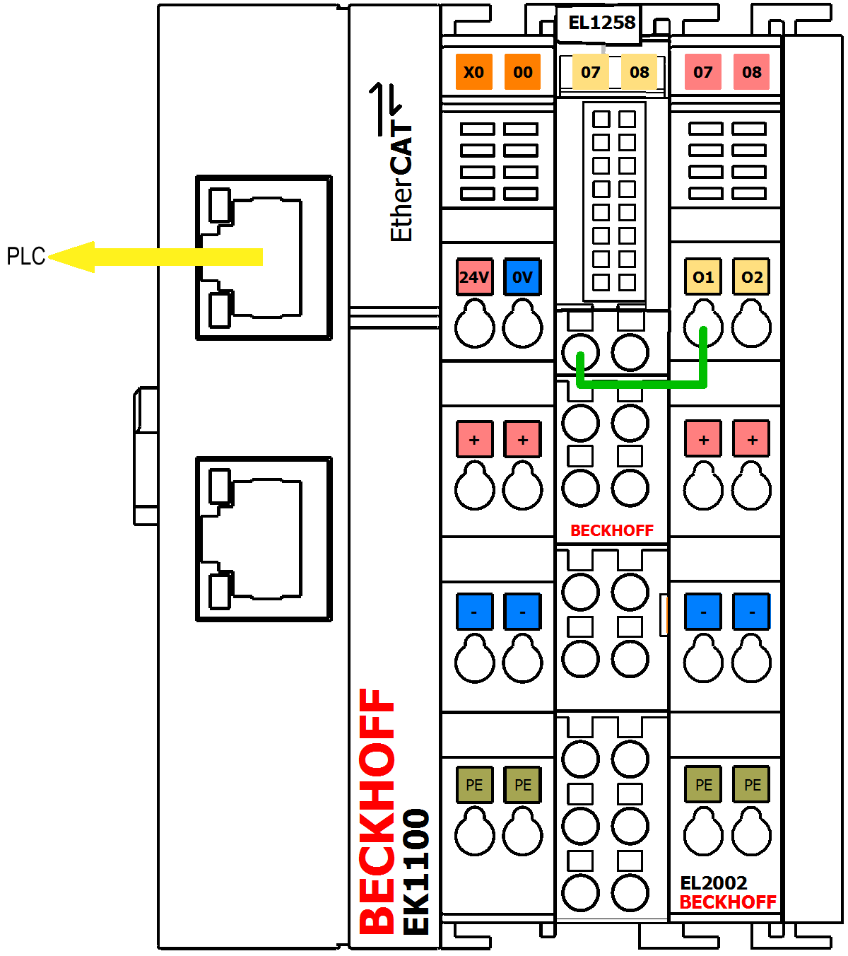 Fig.186: Recommended structure for the EL1258 sample program
 Download: EL1258_sample program
The MTI settings for the EL1258 are as follows:
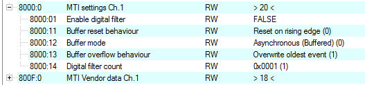 Fig.187: CoE object 0x8000 (MTI settings ch.1): Settings for the sample program
To change settings, select the terminal in the Solution Explorer and select the "CoE - online" tab.
Explanatory notes on the sample program
A TwinCAT 3 visualization is used to illustrate the evaluation of binary input signals. Only the basic functionality is described. To this end, Visualization_1 merely represents a timestamp difference of two events at the input of channel 1 of the EL1258 (input bit 0 → 1 → 0):
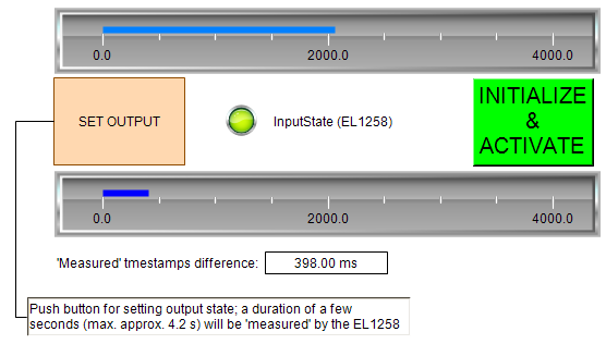 Fig.188: Sample program EL1258 / Visualization_1: simple time measurement based on two state changes
A digital output terminal, whose output is directly connected to input channel 1 of the EL1258, switches the output with "SET OUTPUT". The user presses the button for any length of time; the elapsed time is shown in the upper bar-graph display, while the lower bar-graph display shows a time span determined by the timestamps of the EL1258.
Like Visualization_2, this is used for continuous output of a bit pattern or a pseudo-random sequence. All variations are possible here, with the intention to illustrate the behavior of the EL1258, including a reconstruction of the bit pattern using the time stamps of the received events (right side):
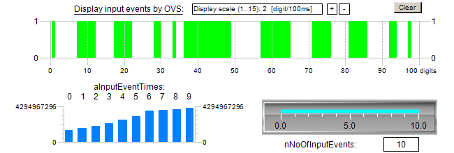 Fig.189: Sample program EL1258 / Visualization_2: Display of incoming events in chronological order according to the timestamps of the EL1258
Using the bit pattern defined in the POU "PulseOutputs" (left side):

This bit pattern is stored in the constant "nOutValueInit" as a 64-bit value in binary format and can be changed here with another bit sequence. Furthermore, Visualization_2 illustrates a basic procedure for processing the input signals of the EL1258: after processing current times (aInputEventTimes) and their associated states (aInputEventState) within the program, the system checks whether there are still events in the buffer (nEventsInInputBuffer). This is illustrated as follows:
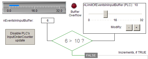 Fig.190: Query of the "EventInInputBuffer" of the EL1258: Are there any other events stored in the terminal?
"LimitOfEventsInInputBuffer" can be used to specify from when the buffered events should be transferred to the readable PDOs of the terminal. The implementation in MAIN is represented here by the graphically displayed conditional branching and is intended to show that events stored in the terminal are passed on to the PDOs "externally" by incrementing the "InputOrderCounter".
 | Usage of the example program for EL1259 If the example program shall be used for the EL1259, this terminal have to be set into the configuration instead of the EL1258. All PDO bound to the selected input channel have to be linked with the respective program variables. As shown in figure “CoE object 0x8000 (MTI settings ch.1): Settings for the sample program” above, this device requires an equivalent configuration of channel 1 in CoE object 0x8080. |