Output protection during DC switching of inductive loads (overvoltage limitation)
The digital outputs can be used to switch inductive loads, provided that the energy generated during shutdown is dissipated outside the output. The focus of this consideration is on DC-excited loads (typically 5-24 V DC in industry).
Two fields need to be considered.
- Selection of the protective circuit
- Dimensioning the protective circuit
Inductive loads, such as electromechanical relays, contactors or coils, want to remain in their steady state. If the driver (in our example, the digital output from Beckhoff) stops supplying (by being shutdown), the coil will attempt to allow the current to continue flowing due to its stored magnetic energy. It will then "draw" current from the switching output until the magnetic energy is used by parasitic effects. Without additional measures, a high negative voltage (ranging from several tens to thousands of volts, depending on the load) will occur at the switch output due to the self-induction of the coil. This voltage may result in immediate destruction, or repeated occurrences may cause damage. This applies to semiconductor switching outputs (e.g. EL20xx, EL28xx) as well as relay switching outputs (e.g. EL26xx).
Another disadvantage is that this short, high voltage (also known as a "transient") in the kV/µs range generates significant electromagnetic radiation, causing capacitive interference with neighboring devices and lines. Any damping/suppression components should therefore preferably be placed close to the load (i.e., at the point of origin) so that the transients do not even reach the line.
The following measures can be considered, among others. The attached figures show a relay as an example of a common inductive load.
1. Resistance parallel to inductance
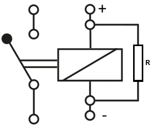 Fig.32: Resistance parallel to inductance
It is a very simple method, but one in which current constantly flows uselessly past the coil. This circuit is also known as snubbers.
Note: An RC element is common for AC excitation. However, it must be designed very precisely to ensure optimum operation (time behavior, power loss).
2. Solution with semiconductors
- Short-circuit diode on the inductance, free-wheeling diode
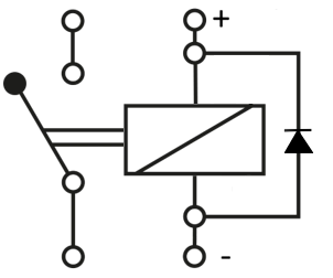 Fig.33: Short-circuit diode on the inductance, free-wheeling diode
This solution is often the most appropriate for DC excitation and should be considered first. It reliably protects the output as the self-induction voltage is limited to approx. -1 V (even less if a Schottky diode is used). In addition, it is usually easy to dimension, as hardly any power is dissipated via the diode with small DC inductances.
However, the induction voltage only drops very slowly (a few ms), which can be disadvantageous for relays as a switching load or if fast shutdown is desired.
Note: In the event of expected power failures, however, this latching effect may be desirable to prevent the relay from dropping too early.
- Varistor or Zener diode, ideally a bidirectional suppressor diode (TVS= Transient Voltage Suppressor)
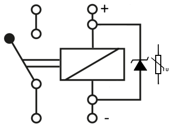 Fig.34: Example circuit with Zener diode
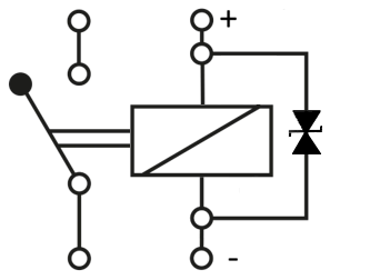 Fig.35: Example circuit with bidirectional suppressor diode (Transient Voltage Suppressor)
This solution ensures that the load drops relatively quickly (a relay may be required). The coil is not short-circuited, but must dissipate its energy at a higher voltage. This means that the magnetic field can collapse quickly. It should be noted that the semiconductor can become very warm.
The reverse voltage of the Zener diode must be significantly higher than the regular operating voltage, otherwise normal operation is not possible. In a 24 V industrial system (usually up to approx. 29 V are permissible), for example, it is 35 V. Such diodes are also often used in 24 V DC power supplies to temporarily short-circuit transients!
Unfortunately, designing a semiconductor-based overvoltage limitation is not trivial. The following points must be observed:
- How much (magnetic) energy must be dissipated?
If the inductance of the load and the nominal current are known, the energy stored in the coil can be calculated using the formula W [J] = 1/2 * L [H] * I^2 . Unfortunately, many manufacturers do not specify the inductance, so it may have to be determined by measurement. - What breaking energy [J, Ws, VAs] can the switching output withstand, and is this value sufficient? See Technical data.
- How often must the energy be dissipated (switching frequency)?
- Unfortunately, it is difficult to determine the achievable performance of the protective component because it depends on several factors, including how the generated heat is dissipated (mechanical connection = thermal resistance -> installation costs), the pulse frequency and the tolerable residual voltage level.
- Therefore, the design typically requires an experimental, system-specific approach. This approach can begin with commercially available standard diodes, such as 1N4007/1000 V or TVS 600 W. Alternatively, you can select normative tests, for which a protective component will then be selected experimentally.
Corresponding components are commercially available
- as discrete, wired components from various electronic distributors/shops.
- as ready-to-install DIN rail accessories.
- as a special accessory for sensitive products (e.g. contactors).