EL1252, EL1252-0010, EL1252-0050, EL1252-0060, EL1254 - LEDs and pin assignment
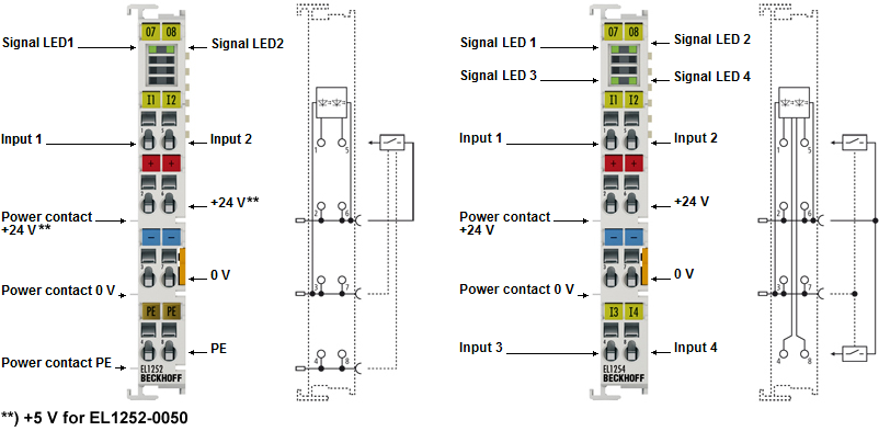 Fig.5: LEDs EL1252-00x0, EL1254
LEDs
LED | Color | Meaning | |
|---|---|---|---|
INPUT 1 | green | off | There is no input signal at the respective input |
on | Input signal at the respective input | ||
*) EL1254 only
Notice | |
EL1252-0050: damage to the terminal possible! When configuring the Bus Terminal system, please note the different potentials on the power contacts (24 VDC and 5 VDC) and, if necessary, use potential isolating terminals or potential feed terminals to separate the potentials! |
EL1252, EL1252-0010, EL1252-0060- pin assignment
Terminal point | Description | |
|---|---|---|
Name | No. | |
Input 1 | 1 | Input 1 |
+ 24 V | 2 | +24 V (internally connected to terminal point 6 and positive power contact) |
0 V | 3 | 0 V (internally connected to terminal point 7 and negative power contact) |
⏚ | 4 | Ground |
Input 2 | 5 | Input 2 |
+ 24 V | 6 | +24 V (internally connected to terminal point 6 and positive power contact) |
0 V | 7 | 0 V (internally connected to terminal point 3 and negative power contact) |
⏚ | 8 | Ground |
EL1252-0050 - pin assignment
Terminal point | Description | |
|---|---|---|
Name | No. | |
Input 1 | 1 | Input 1 |
+ 5 V | 2 | +5 V (internally connected to terminal point 6 and positive power contact) |
0 V | 3 | 0 V (internally connected to terminal point 7 and negative power contact) |
⏚ | 4 | Ground |
Input 2 | 5 | Input 2 |
+ 5 V | 6 | +5 V (internally connected to terminal point 6 and positive power contact) |
0 V | 7 | 0 V (internally connected to terminal point 3 and negative power contact) |
⏚ | 8 | Ground |
EL1254 - pin assignment
Terminal point | Description | |
|---|---|---|
Name | No. | |
Input 1 | 1 | Input 1 |
+ 24 V | 2 | +24 V (internally connected to terminal point 6 and positive power contact) |
0 V | 3 | 0 V (internally connected to terminal point 7 and negative power contact) |
Input 3 | 4 | Input 3 |
Input 2 | 5 | Input 2 |
+ 24 V | 6 | +24 V (internally connected to terminal point 6 and positive power contact) |
0 V | 7 | 0 V (internally connected to terminal point 3 and negative power contact) |
Input 4 | 8 | Input 4 |