Notes to the NAMUR switching amplifier of the terminal
The EL105x terminal is developed with regard to its input sided, functional voltage‑to‑current characteristic in compliance with the definitions of IEC 60947‑5‑6.
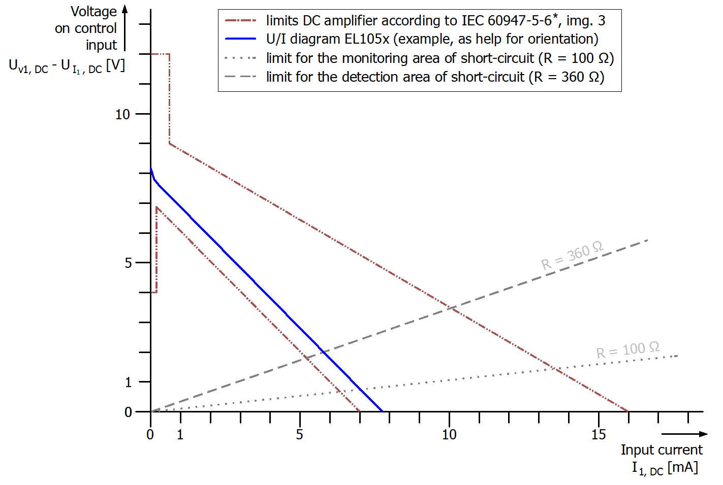
(*Source of the standard limits: IEC 60947‑5‑6, edition 1999)
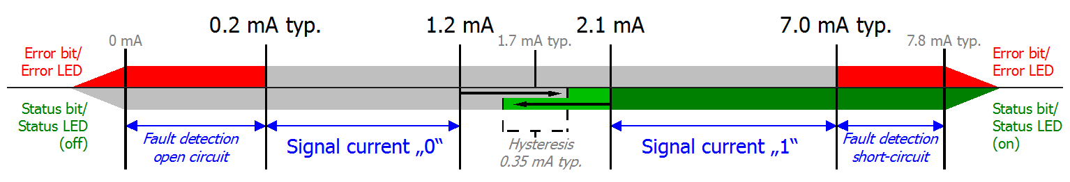
Status bit, Status LED, Error bit, Error LED and switching hysteresis of the terminal together with NAMUR‑limits is represented by the image as follows:
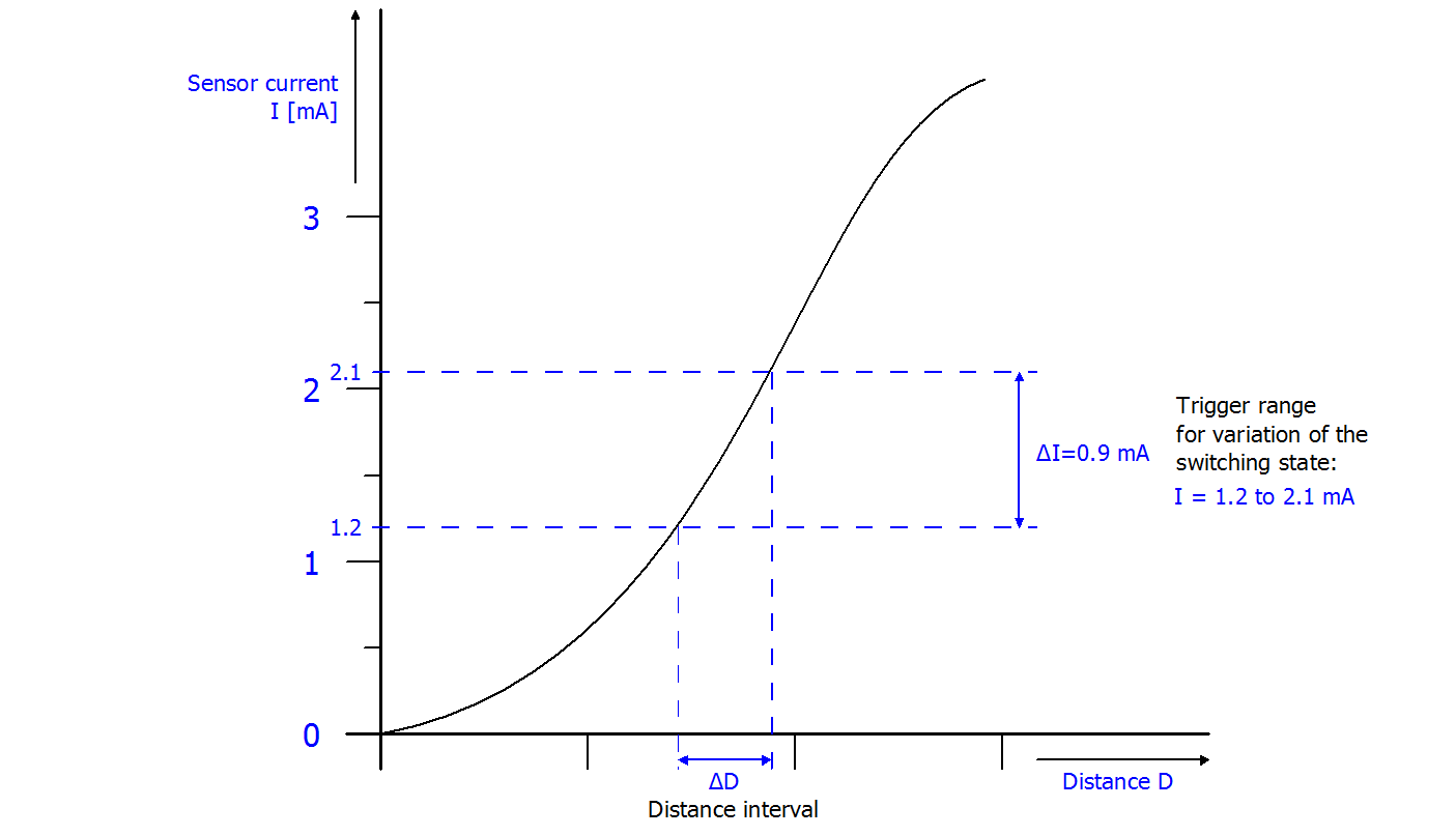
A program of a control can evaluate the "Status bit" for the binary state and the "Error bit" of the terminal for error detection. Accordingly, in addition to the active wire break or short circuit detection of the sensor, e.g. switching paths differences of a sensor by a continuous sensor characteristic can be unique distinguished as follows: