LEDs and connection
Status LEDs
LED | Display | State | Description | |
|---|---|---|---|---|
RUN | green | off | Init | The bus coupler is in initialization state |
flashing | Pre-Operational | The bus coupler is in pre operational state | ||
single flash | Safe-Operational | The bus coupler is in safe operational state | ||
on | Operational | The bus coupler is in operational state | ||
flickers | Bootstrap | A new firmware will be loaded | ||
US | off | - | No 24 VDC operating voltage for US available on bus coupler | |
green | - | Incoming 24 VDC operating voltage for US available on the bus coupler within the permissible range | ||
red | - | Under voltage approx. < 20.3 V | ||
UP | off | - | No 24 VDC operating voltage for UP available on bus coupler | |
green | - | Incoming 24 VDC operating voltage for UP available on the bus coupler within the permissible range and outgoing UP on power contacts OK | ||
red | - | Incoming 24 VDC operating voltage for UP or outgoing UP on power contacts: Under voltage approx. < 20.3 V | ||
DEV | off | - | Normal operation | |
yellow | - | Over temperature within device > 85°C | ||
EtherCAT Link LEDs (EKM1101 only)
LED | Display | State | Description | |
|---|---|---|---|---|
LINK/ACT | green | off | - | No connection on the incoming EtherCAT strand |
on | linked | Preceding EtherCAT device connected | ||
flashing | active | Communication with preceding EtherCAT device | ||
LINK/ACT | green | off | - | No connection on the outgoing EtherCAT strand |
on | linked | Following EtherCAT device connected | ||
flashing | active | Communication with following EtherCAT device | ||
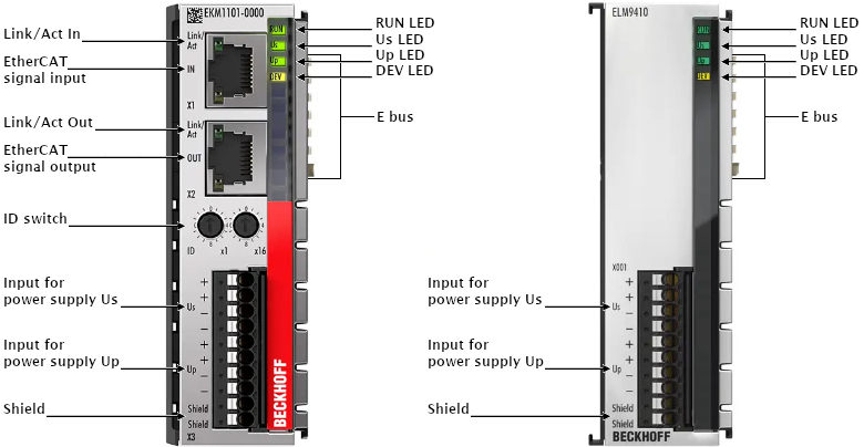
Connection EKM1101, ELM9410
EKM1101: ELM9410: | Description | |
|---|---|---|
Indication | No. | |
+US | 1, 2 | Supply input + 24 V for Us (E Bus; terminal no. 1 and 2 internal connected) |
-US | 3, 4 | Supply input 0 V for Us (E Bus; terminal no. 3 and 4 internal connected) |
+UP | 5, 6 | Supply input + 24 V for UP (Power contacts; terminal no. 5 and 6 internal connected) |
-UP | 7, 8 | Supply input 0 V for UP (Power contacts; terminal no. 7 and 8 internal connected) |
Shield | 9, 10 | Grounding connector to DIN rail or rather housing (terminal no. 9 and 10 internal connected) Note: PE accessible under cover as screw connection |