EK9300 - IO-LINK
Description
The EK9300 (from firmware 6) supports the IO-Link master EL6224 (EtherCAT Terminal) and EP6224 (EtherCAT Box). The GSDML file (from version GSDML-V2.32-beckhoff-EK9300-20160408.xml) includes this IO-Link master. Each IO-Link device is addressed as a submodule and must be configured via the GSDML file.
 | Use with the EL6224/EJ6224 If the EL6224/EJ6224 IO-Link terminal is used, the process data 83 bytes input or 83 bytes output must not be exceeded. This means that the process data of all 4 IO-Link channels added together must not exceed this value. It is therefore not possible to use 32-byte modules 4 times, since these are larger than 83 bytes with 4 x 32 bytes. This does not apply to the Beckhoff EP or EPP boxes with IO-Link. |
Task
Connection of an IO-Link sensor to an EK9300.
Configuration of the process data
Each IO-Link device is added as a submodule. For each IO-Link device a submodule is used. The process data size of the submodule must always be equal to or greater than that of the IO-Link device and must not be less.
If not all IO-Link channels are used, empty channels should be entered. For example, if sensors are only connected to inputs 2 and 4 of the IO-Link master, while inputs 1 and 3 are unused, first enter an empty channel as submodule, then the sensor at input 2, then another empty channel and finally the sensor at input 4. The first submodule used by the IO-Link master is a diagnostics module. This is always present when the EL6224/EP6224 is added. This submodule contains the status of all connected IO-Link devices. If the sensor is in IO-Link data exchange, this is indicated via the corresponding byte (0x03 means all OK).
Information on the status byte:
0x_0 = Port disabled
0x_1 = Port in std dig in
0x_2 = Port in std dig out
0x_3 = Port in communication OP
0x_4 = Port in communication COMSTOP / dig in Bit (only in std. IO Mode)
0x_8 = Process Data Invalid Bit
0x1_ = Watchdog detected
0x2_ = internal Error
0x3_ = invalid Device ID
0x4_ = invalid Vendor ID
0x5_ = invalid IO-Link Version
0x6_ = invalid Frame Capability
0x7_ = invalid Cycle Time
0x8_ = invalid PD in length
0x9_ = invalid PD out length
0xA_ = no Device detected
0xB_ = error PreOP/Data storage
Regarding the process data size of an IO-Link device, please refer to the documentation or consult the manufacturer.
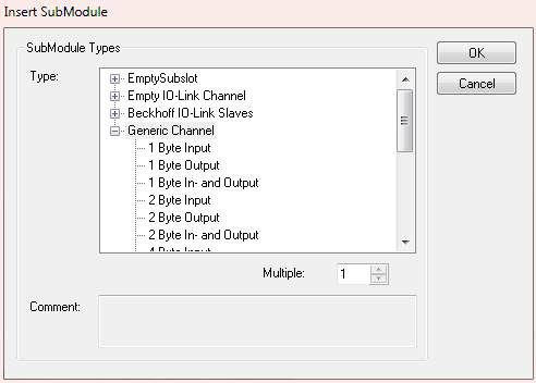 Fig.51: Inserting a "generic channel" (in the case of IO-Link devices from other manufacturers)
IO-Link devices from Beckhoff are automatically added with the required parameters. For devices from other manufacturers please use a generic channel and select the process data size.
Configuration of the IO-Link device
The minimum settings required for operating an IO-Link device are:
IO-Link version: Generally 1.1; enter 11
Frame capability: Generally 1
Min. cycle time: Generally 2.3 ms, i.e. 23
Process data in / Out length: Variable (number in bits), for a size of 2 bytes input enter 16 for "Process data in length".
If the IO-Link slave has more than 16 bits, the high bit is set (BIT 7 TRUE), then the data length is specified in bytes + 1, example 4 bytes of process data, a 0x83 (131 dec) must be specified, 0x8x then stands for counting bytes and the length is then 3 (=4 bytes). A maximum of 32 bytes is then possible here.
Master control: set to IO-Link
All other settings are optional.
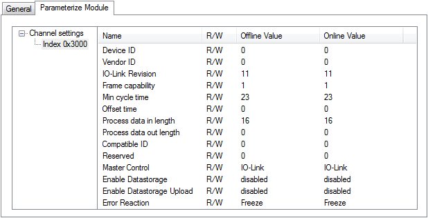 Fig.52: Configuration of the IO-Link device
Reading/writing of parameters
Each IO-Link device has parameters that can be read or written. The EK9300 supports this function from firmware 10. The EK9300 has implemented the IO-Link profile from this firmware.
Many manufacturers of PROFINET controllers support the IO-Link profile with corresponding devices that you can use. For more information, please contact your controller manufacturer.
| IO-Link devices for PROFINET Beckhoff currently does not offer IO-Link devices for PROFINET, since we assume that if Beckhoff products are used, Beckhoff IO-Link via EtherCAT will also be used. For EtherCAT Beckhoff offers ADS blocks, or also IO-Link dialogs for simple commissioning, as well as working with and using the IO-Link description files. |
Here is an example from the Siemens TIA world:
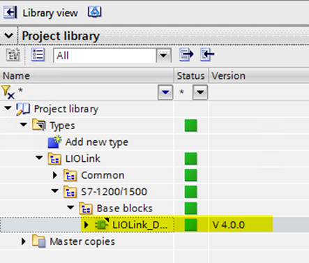 Fig.53: Inserting IO-Link devices in the TwinCAT tree
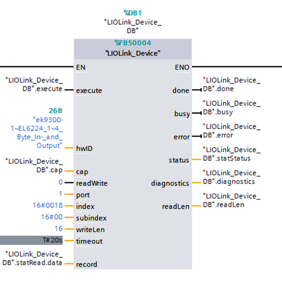 Fig.54: Structure of an IO-Link device