Commissioning EL72x1-xxxx
The EK9300 supports the servo terminals with the "Drive Motion Control" mode. This mode enables an axis to move independently to a position assigned from the process data. The setpoint calculations, which are usually done by the NC, are done in DMC mode by the terminal itself.
The commissioning of an EL7201-0010 on the EK9300 is to be shown by means of an example.
Requirement:
- Min. EK9300 firmware version "14(V0.59)"
- Min. GSDML Version "GSDML-V2.34-BECKHOFF-EK9300-20190904.XML"
- Min. EL72xx-xxxx firmware version 19
- Min. EL72xx-xxxx esi version 30
Hardware used
- EK9300 with firmware version 14(V0.59)
- EL7201-0010 with firmware version 19 and EL7201 ESI File EL7201-0010-9999.xml
- ZK4704-0401-0000 (motor cable)
- AM8112-0F20-0000
Configuration
First, the EK9300 and the EL7201-0010 must be added to the configuration. See: Appending PROFINET devices
To ensure that the terminal uses the correct motor, it is recommended to read the motor name plate with the terminal. For this the parameter entries "Enable auto config", "Reconfig identical motor" and "Reconfig non-identical motor" in the parameter settings "FB OCT SettingsCh1 - Index 0x3008" of the terminal must be changed to "TRUE".
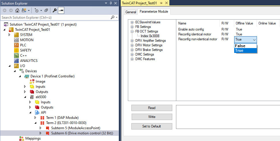 Fig.29: Parameter settings for automatic readout of the motor name plate used
The terminal reads the name plate of the motor and sets the motor-specific parameters automatically. The default motor settings are not used any further and can be read back if required.
Mapping of the EL7201-0010 in "Drive Motion Control" format
INPUTS (64 bytes):
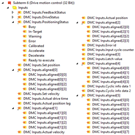 Fig.30: Drive Motion Control Inputs
Name | Size (variable) | Bit offset |
|---|---|---|
DMC Inputs.FeedbackStatus (16-bit array) | ||
Latch extern valid | BIT (BOOL) | 0.1 |
Set counter done | BIT (BOOL) | 0.2 |
Status of extern latch | BIT (BOOL) | 1.4 |
DMC Inputs.DriveStatus (16-bit array) | ||
Ready to enable | BIT (BOOL) | 2.0 |
Ready | BIT (BOOL) | 2.1 |
Warning | BIT (BOOL) | 2.2 |
Error | BIT (BOOL) | 2.3 |
Moving positive | BIT (BOOL) | 2.4 |
Moving negative | BIT (BOOL) | 2.5 |
Digital input 1 | BIT (BOOL) | 3.3 |
Digital input 2 | BIT (BOOL) | 3.4 |
DMC Inputs.PositioningStatus (16-bit array) | ||
Busy | BIT (BOOL) | 4.0 |
In-Target | BIT (BOOL) | 4.1 |
Warning | BIT (BOOL) | 4.2 |
Error | BIT (BOOL) | 4.3 |
Calibrated | BIT (BOOL) | 4.4 |
Accelerate | BIT (BOOL) | 4.5 |
Decelerate | BIT (BOOL) | 4.6 |
Ready to execute | BIT (BOOL) | 4.7 |
DMC Inputs.Set position | DWORD (32-bit) | 6-9 |
DMC Inputs.aligned [0] | DWORD (32-bit) | 10-13 |
DMC Inputs.Set velocity | WORD (16-bit) | 14-15 |
DMC Inputs.Actual drive time | DWORD (32-bit) | 16-19 |
DMC Inputs.Actual position lag | DWORD (32-bit) | 20-23 |
DMC Inputs aligned [1] | DWORD (32-bit) | 24-27 |
DMC Inputs.Actual velocity | WORD (16-bit) | 28-29 |
DMC Inputs.Actual position | DWORD (32-bit) | 30-33 |
DMC Inputs.aligned [2] | DWORD (32-bit) | 34-37 |
DMC Inputs.Error Id | DWORD (32-bit) | 28-41 |
DMC Inputs.Input cycle counter | Byte (8 bit) | 42 |
DMC Inputs.aligned [3] | Byte (8 bit) | 43 |
DMC Inputs.Latch value input | DWORD (32-bit) | 44-47 |
DMC Inputs.aligned [4] | DWORD (32-bit) | 48-51 |
DMC Inputs. Cycle info data1 | WORD (16-bit) | 52-53 |
DMC Inputs.Cycle info data2 | WORD (16-bit) | 54-55 |
DMC Inputs.aligned [5] | LWORD (64-bit) | 56-63 |
OUTPUTS (40 bytes):
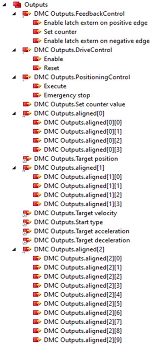 Fig.31: Drive Motion Control Outputs
Name | Size (variable) | Bit offset |
|---|---|---|
DMC Outputs.FeedbackControl (16-bit array) | ||
Latch extern valid | BIT (BOOL) | 0.1 |
Set counter done | BIT (BOOL) | 0.2 |
Status of extern latch | BIT (BOOL) | 1.4 |
DMC Outputs.DriveControl (16-bit array) | ||
Enable | Bit (BOOL) | 2.0 |
Reset | Bit (BOOL) | 2.1 |
DMC Outputs.PositioningControl (16-bit array) | ||
Execute | BIT (BOOL) | 4.0 |
Emergency Stop | BIT (BOOL) | 4.1 |
DMC Outputs.Set counter value | DWORD (32-bit) | 6-9 |
DMC Outputs.aligned [0] | DWORD (32-bit) | 10-13 |
DMC Outputs.Target position | DWORD (32-bit) | 14-17 |
DMC Outputs.aligned [0] | DWORD (32-bit) | 18-21 |
DMC Outputs.Target velocity | WORD (16-bit) | 22-23 |
DMC Outputs.Start Type | WORD (16-bit) | 24-25 |
DMC Outputs.Target acceleration | WORD (16-bit) | 26-27 |
DMC Outputs.Target deceleration | WORD (16-bit) | 28-29 |
DMC Outputs.aligned [0] | 10 bytes | 30-39 |
Program sequence
- At the beginning it must be ensured that the EK9300 is in data exchange.
- The diagnostics in TwinCAT, the status process data or the LEDs of the EK9300 can be used for this purpose.
- As soon as the EK9300 is in data exchange, the connected EL7201-0010 can be checked for correct function.
- For this purpose, the error bits in the "Drive" and "PositioningStatus" are checked. If both status bits are equal to "FALSE", the "Ready to enable" bit under "DriveStatus" is checked. If this is equal to "TRUE" the "Enable bit" under "DriveControl" can be set.
- If the "Ready to execute" bit equals "TRUE", the first motion command can be started.
- For this, the position1) must be set via "DMC Outputs.Target position", the velocity2) via "DMC Outputs.Target velocity", the starting acceleration3) via "DMC Outputs.Target acceleration" and the deceleration3) via "DMC Outputs. Target deceleration" as well as the start type4) can be transferred to the terminal via "DMC Outputs.Start Type".
- The "Execute" bit under "DriveControl" starts and executes the command.
- The "Busy" bit under "DriveStatus" remains "TRUE" until the motion command has been processed.
- If the axis is in position, this is signaled by the "In-Target" bit. Furthermore the bit "Busy" changes from "TRUE" to "FALSE".
- As soon as the "Busy" bit changes to "FALSE", the "Execute" bit must be set to "FALSE" by the user.
- If "Execute" is set to "FALSE" while "Busy" equals "TRUE", the current motion command is interrupted and the axis stops.
- To transfer a new motion command, the "Ready to execute" bit must be checked again.
1) The position of one revolution is 0x0010_0000 220 |
ABSOLUTE | 0x0001 | Absolute positioning to a specific target position |
RELATIVE | 0x0002 | Relative positioning to a calculated target position; a specified position difference is added to the current position |
ENDLESS_PLUS | 0x0003 | Endless travel in the positive direction of rotation (direct specification of a velocity) |
ENDLESS_MINUS | 0x0004 | Endless travel in the negative direction of rotation (direct specification of a velocity) |
MODULO_SHORT | 0x0105 | Modulo positioning along the shortest path to the modulo position (positive or negative), calculated by the "modulo factor" |
MODULO_PLUS | 0x0205 | Modulo positioning in the positive direction of rotation to the calculated modulo position |
MODULO_MINUS | 0x0305 | Modulo positioning in the negative direction of rotation to the calculated modulo position |
CALI_PLC-CAM | 0x6000 | Start a calibration with cam (digital inputs) |
CALI_ON_BLOCK | 0x6200 | Start a calibration "on block". |
CALI_SET_POS | 0x6E00 | Set as calibrated, do not change position |
CALI_CLEAR_POS | 0x6F00 | Delete calibration bit |
 | Creating a task for commissioning via TwinCAT For commissioning via TwinCAT with our PROFINET controllers, a separate task must be created for the outputs, otherwise the values will not be processed correctly. |
Servo terminal with STO input:
If the terminal in use is to have an STO input, this can lead to an error if it is not supplied with power.
A distinction must be made here between two cases, i.e. which error occurs.
- The STO input of the terminal is not supplied with 24 V and the axis is to be switched on. This case is signaled by a "TRUE" at the "Warning Bit" under "DriveStatus" and by a warning in the "DiagHistory" in TwinCAT. This message cannot be read in the TIA portal.
- The voltage at the STO input of the terminal drops during operation. Thereafter, the error bit "Error" under "DriveStatus" should change to "TRUE" and under "Error ID" the value 0x841Chex or 33820dec should be displayed.
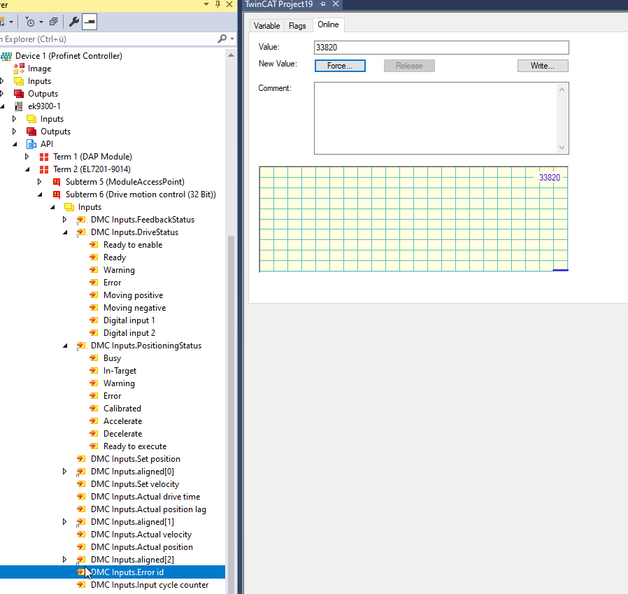 Fig.32: Display of the Error ID if the STO input is absent
It is possible to show the state of the STO input in the process data. For this purpose, the option "Input level" must be selected in the parameter settings of the terminal under "DRV Amplifier Settings Ch. 2 - Select Info data x". The state is then displayed in the eighth bit of the "Cyclic info data x".
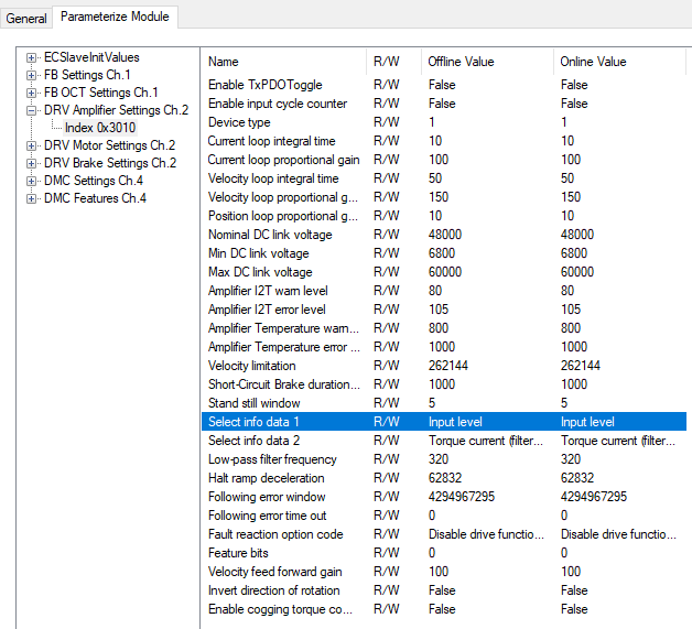
Parameter settings for showing the STO input in the process data
Using the EL7201-0010 via the TIA portal
- Configuration
- Hardware used in this example: Simatic S7-1500 CPU 1516F-3 PN/DP &ES7 516-3FN01-0AB0
- The hardware required is added under "Device & Networks"
- Ensuring error-free communication
- To check whether communication between the S7-1500 and the EK9300 works without error, the program must first be compiled and loaded onto the controller.
- Subsequently, all LEDs on the EK9300 must light up green. If this is not the case, there is no or faulty communication between the controller and the device. If all LEDs are lit up green, you can connect to the controller via "Go online".
- Assignment of the process data to the respective inputs and outputs
- First of all, it must be determined which input and output addresses of the EL7201-0010 have been assigned by the TIA portal. To do this, the EK9300 must be selected under "Network View", and the assigned input and output addresses are displayed on the right-hand side.
- It must then be checked which process data corresponds to which input or output.
- In the graphic above, you can see that there is an offset of 4 for the input process data. This means that the process data "DMC Inputs.FeedbackStatus.Latch extern valid" in the TIA portal has the input address "4.1".
- The output process data in this sample have no offset at all; i.e. the "DMC Outputs.FeedbackControl.Latch extern valid" has the output address "0.1".
- Furthermore, the respective byte size of the process data is shown in the graphic.
- To control the assignments of the inputs, the program must be compiled, loaded to the controller and connected online. Subsequently, the variable table must be opened and the observation mode must be activated.
- If the terminal is connected correctly and there is no error, the input "InputCycleCounterInput" should toggle and the input "ReadyToEnableDriveInput" should be "TRUE".
- Automatic readout of motor data via CoE parameters
- In order to read the motor data directly from the electronic identification plate, the CoE parameters under "FB OCT Settings Ch.1" must all be set to "TRUE".
- For this purpose, the device configuration must be opened under "Device & Network".
- The EK9300 must then be double-clicked with the left mouse button.
- As a result, the EK9300 can be seen with whole modules on the right side. To access the CoE parameters of the EL7201-0010, the Drive Motion Control module must be selected.
- Afterwards, "Module parameters" must be selected under "Properties". The CoE parameter settings of the terminal should then be visible.
- The parameters "Enable auto config", "Reconfig identical motor" and "Reconfig non-identical motor" must be set to TRUE. To write the values, the project must be compiled once and reloaded to the controller.
- An online access to the CoE parameters does not work. The values can only be changed offline.
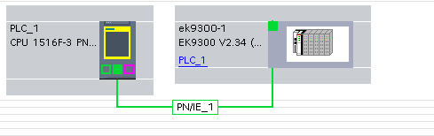 Fig.33: TIA Portal "Device & Networks" view
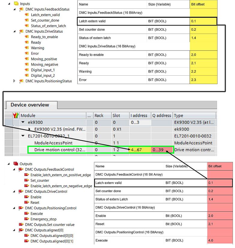 Fig.34: Example process data of the EL7201 in the TIA portal
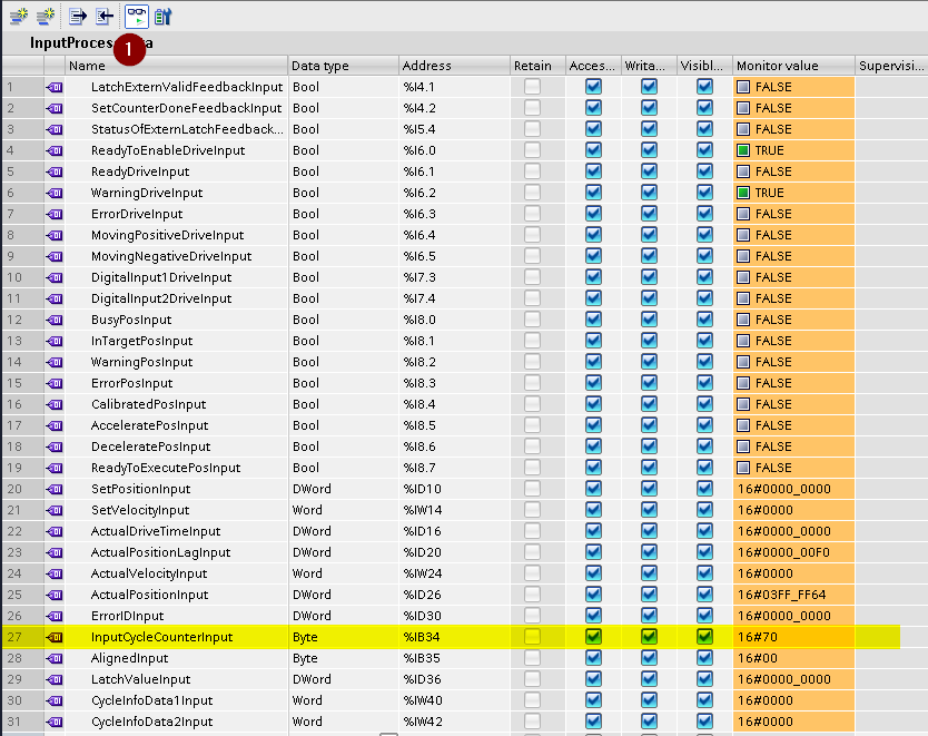 Fig.35: View TIA Portal, check correct assignment of process data and addresses
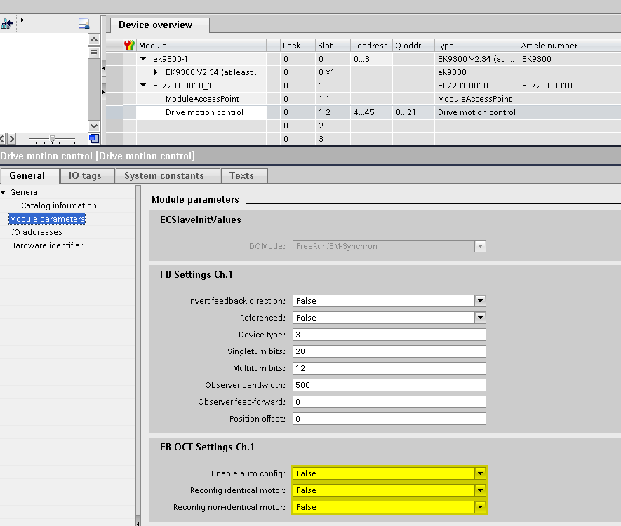 Fig.36: TIA portal "Properties" - "Module parameters" view