Cabling
Physical aspects of the data transmission are defined in the PROFIBUS standard (see PROFIBUS layer 1: Physical Layer).
The types of area where a fieldbus system can be used is largely determined by the choice of the transmission medium and the physical bus interface. In addition to the requirements for transmission security, the expense and work involved in acquiring and installing the bus cable is of crucial significance. The PROFIBUS standard therefore allows for a variety of implementations of the transmission technology while retaining a uniform bus protocol.
Cable-based transmission:
This version, which accords with the American EIA RS-485 standard, was specified as a basic version for applications in production engineering, building management and drive technology. A twisted copper cable with one pair of conductors is used. Depending on the intended application area (EMC aspects should be considered) the shielding may be omitted.
Two types of conductor are available, with differing maximum conductor lengths (see the RS485 table).
RS-485 transmission according to the PROFIBUS standard | |
|---|---|
Network topology | Linear bus, active bus terminator at both ends, stubs are possible. |
Medium | Shielded twisted cable, shielding may be omitted, depending upon the environmental conditions (EMC). |
Number of stations | 32 stations in each segment with no repeater. Can be extended to 125 stations with repeater |
Max. bus length without repeater | 100 m at 12 Mbit/s |
Max. bus length with repeater | Repeaters can increase the bus length up to 10 km. The number of repeaters possible is at least 3, and, depending on the manufacturer, may be up to 10. |
Data transfer rate (adjustable in steps) | 9.6 kbit/s; 19.2 kbit/s; 93.75 kbit/s; 187.5 kbit/s; 500 kbit/s; 1500 kbit/s; 12 Mbit/s |
Connector | 9-pin D sub connector for IP20 |
Cable-related faults
Note the special requirements on the data cable for bit rates greater than 1.5 Mbit/s. The correct cable is a basic requirement for correct operation of the bus system. If a simple 1.5 Mbit/s cable is used, reflections and excessive attenuation can lead to some surprising phenomena. It is possible, for instance, for a connected PROFIBUS station not to achieve a connection, but for it to be included again when the neighboring station is disconnected. Or there may be transmission errors when a specific bit pattern is transmitted. The result of this can be that when the equipment is not operating, PROFIBUS works without faults, but that there are apparently random bus errors after start-up. Reducing the bit rate (< 93.75 kbit/s) corrects this faulty behavior.
If reducing the bit rate does not correct the error, then in many cases this can indicate a wiring fault. The two data lines may be crossed over at one or more connectors, or the termination resistors may not be active, or they may be active at the wrong locations.
 | Preassembled cable from BECKHOFF Installation is made a great deal more straightforward if preassembled cables from BECKHOFF are used! Wiring faults are avoided, and commissioning is more rapidly completed. The BECKHOFF range includes fieldbus cables, power supply cables, sensor cables and accessories such as termination resistors and T-pieces. Connectors and cables for field assembly are nevertheless also available. |
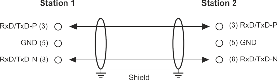
The following diagram shows the cabling between two stations, as well as the D sub connection assignment:
| Termination resistors In systems with more than two stations all devices are wired in parallel. It is essential that the bus cables are terminated with resistances at the conductor ends in order to avoid reflections and associated transmission problems. |
Distances
The bus line is specified in EN 50170. This yields the following lengths for a bus segment.
Bit rate in kbits/sec | 9.6 | 19.2 | 93.75 | 187.5 | 500 | 1500 | 12000 |
|---|---|---|---|---|---|---|---|
Cable length in m | 1200 | 1200 | 1200 | 1000 | 400 | 200 | 100 |
Stubs up to 1500 kbit/s <6.6 m; at 12 Mbit/s stub segments should not be used.
Bus segments
A bus segment consists of at most 32 devices. 125 devices are permitted in a PROFIBUS network. Repeaters are required to refresh the signal in order to achieve this number. Each repeater is counted as one device.
IP-Link is the subsidiary bus system for Fieldbus Boxes, whose topology is a ring structure. There is an IP-Link master in the coupler modules (IP230x-Bxxx or IP230x-Cxxx) to which up to 120 extension modules (IExxxx) may be connected. The distance between two modules may not exceed 5 m. When planning and installing the modules, remember that because of the ring structure the IP-Link master must be connected again to the last module.
Installation guidelines
When assembling the modules and laying the cables, observe the technical guidelines provided by the PROFIBUS User Organization (PROFIBUS Nutzerorganization e.V.) for PROFIBUS DP/FMS (see: www.profibus.de).
Check the PROFIBUS cable
A PROFIBUS cable (or a cable segment when using repeaters) can be checked with a few simple resistance measurements. The cable should meanwhile be removed from all stations:
- Resistance between A and B at the start of the line: approx. 110 Ohm
- Resistance between A and B at the end of the line: approx. 110 Ohm
- Resistance between A at the start and A at the end of the line: approx. 0 Ohm
- Resistance between B at the start and B at the end of the line: approx. 0 Ohm
- Resistance between shield at the start and shield at the end of the line: approx. 0 Ohm
If these measurements are successful, the cable is okay. If, in spite of this, bus malfunctions still occur, this is usually a result of EMC interference. Observe the installation notes from the PROFIBUS User Organization (www.profibus.com).