EK1310 - Configuration by means of the TwinCAT System Manager
TwinCAT tree
Enter the EK1310 EtherCAT P extension as an EtherCAT device in the TwinCAT System Manager in Config mode under Devices. Any Terminals already connected to the network can also be read. This will cause all the Bus Couplers with Bus Terminals and their configurations to be loaded. You can then adapt these to meet your requirements.
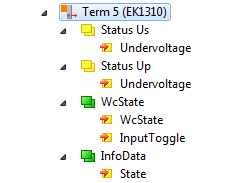
Meaning of the PDO identifier
PDO identifier | Type | State | Description |
|---|---|---|---|
Status UP (Undervoltage) | Bit | 0 | Peripheral voltage for Actors UP >= 19.4 V, no overload/ no case of short circuit |
1 | Peripheral voltage for Actors UP < 19.4 V or overload/ case of short circuit (output current > 3 A) | ||
Status US (Undervoltage) | Bit | 0 | System- and Sensor supply US >= 19.4 V, no overload/ no case of short circuit |
1 | System- and Sensor supply US < 19.4 V or overload/ case of short circuit (output current > 3 A) | ||
WcState | Bit | 0/1 | Each datagram of the device indicates its processing state here. This allows monitoring for correct process data communication. |
InputToggle | Bit | 0/1 | Toggles whenever new valid EtherCAT telegram was received |
State | UINT | - | Status display of the “EtherCAT state machine” (see State, Online tab) |
EtherCAT P tab
From TwinCAT 3 Build 4020 TwinCAT has the tab „EtherCAT P“. This tab contains a planning tool to calculate voltages, currents and cable lengths of EtherCAT P system. The figure below shows the tab EtherCAT P when no device is connected to the junction device (A).

If a device is connected to the junction device (A), you can set the cross-section and the length of the EtherCAT P cable in the tab “EtherCAT P“ of the device. See figure below, B).

Are three devices connected to the three ports of the junction device (A), they are displayed as shown in the figure below.

You can display the topology of your EtherCAT P system.
Wire Gauge | Selection of the wire cross-sectional area of the cable which is to be used AWG 22 = 0.34 mm² AWG 24 = 0.22 mm²
|
Length (m) | Indication of the cable length which is to be used |
Check EtherCAT P System | At least one device is connected to the controller, the connected EtherCAT P system can be checked |
Type | Listing of two voltages: Box supply US, Auxiliary voltage UP |
Actual Voltage (V) | The respective voltage at which the system is powered, can be entered manually. The default setting is 24.00 V. |
Min Voltage (V) | The minimum voltage is preset by the device and described in the ESI file. The EtherCAT P system is to be interpreted after this voltage. It is valid not to fall short this voltage. |
Load (A) | The total consumption of the connected sensors / actuators at the device can be specified here, e.g. 100 mA. |
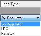
Load Type | The characteristic of the load which is connected to the devices can be selected here. Which of the three options is right for the connected load (Sw regulator, LDO, Resistor), must be taken from the datasheet. In case of doubt please select the default value "Sw Regulator". Sw Regulator: Switching regulators, consume more energy and therefore require an efficient power supply. LDO: Low drop voltage regulator, the energy demand is often small and the heat dissipation is not a problem, e.g. proximity sensor. Resistor: electronic, passive components e.g. relay, coil
|
|
|

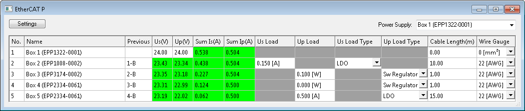
If you click on the button “Check EtherCAT P System”, all devices that are attached to your TwinCAT tree are listed as shown in the following figure.

| No. | The automatically assigned number of the device according to its position in the EtherCAT P strand. |
| Name | Designation of the device in TwinCAT. |
| Previous | Number of the previous device in the EtherCAT P strand and the output port used (A/B/C/D). |
| Us (V), Up (V) | Supply voltage which is present at the input of the device. For device No. 1 You can enter the voltages manually. |
| Sum Is(A), Sum Ip(A) | Sum currents of the supply voltages at the input of the device. |
| Us Load, Up Load | Enter here the total load at the IO ports of the device. |
| Us Load Type, Up Load Type | Choose here the characteristic of the load, which is connected to the IO ports of the device. |
| Cable Length (m) | Enter here the length of the EtherCAT P cable, which is connected to the input of the device. |
| Wire Gauge | Choose here the wire cross-section of the EtherCAT P cable, which is connected to the input of the device.
|
Example with problem case and troubleshooting
The following figure shows the planning of the EtherCAT P system without a problem. All voltages in the column “Supply Voltage (V)” are highlighted in green.
The following figure shows the planning of the EtherCAT P system with a problem. The “Supply Voltage (V)” of Box 5 drops below the “Min. voltage (V)”. The corresponding field is highlighted in red. The error occurs because longer cables (adjustable in “Cable Length (m)”) and also AWG 24 instead of AWG 22 cables (adjustable in “Wire Gauge”) be used.
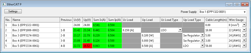
This area offers the following three options to adjust the system so that there is no error:
- Provide a higher voltage: There are max. 28.8 V possible.
- Use an EtherCAT P cable with a larger wire cross sectional area (AWG 22 instead of AWG 24).
- New voltage feed.
State, "Online" tab
Indicates the online status of the terminal.
Value | Description |
|---|---|
0x___1 | Slave in 'INIT' state |
0x___2 | Slave in 'PREOP' state |
0x___3 | Slave in 'BOOT' state |
0x___4 | Slave in 'SAFEOP' state |
0x___8 | Slave in 'OP' state |
0x001_ | Slave signals error |
0x002_ | Invalid vendorId, productCode... read |
0x004_ | Initialization error occurred |
0x010_ | Slave not present |
0x020_ | Slave signals link error |
0x040_ | Slave signals missing link |
0x080_ | Slave signals unexpected link |
0x100_ | Communication port A |
0x200_ | Communication port B |
0x400_ | Communication port C |
0x800_ | Communication port D |
Topology of the EtherCAT P system
You can view the topology of your EtherCAT P system, as described in the figure below:
- 1. In the Click on "Device 1 (EtherCAT)" in the "Solution Explorer"
- 2. Click on the "EtherCAT" tab
- 3. Click on the "Topology" button
- The topology of your EtherCAT P system is displayed.
