Mounting on the mounting rail of the signal distribution board
The EK1110-0043 EtherCAT EJ Coupler is mounted with the Embedded PC (CXxxxx) and the EtherCAT Terminals (ELxxxx) on the mounting rail of the signal distribution board.
 WARNING
Bring the module system into a safe, de-energized state before starting installation, disassembly or wiring of the modules.
Observe the regulations for ESD protection.
Before mounting and demounting, ensure that the signal distribution board is securely connected to the mounting surface. Installation on or removal from an unsecured signal distribution board may result in damage to the board.
Mounting the EtherCAT EJ Coupler
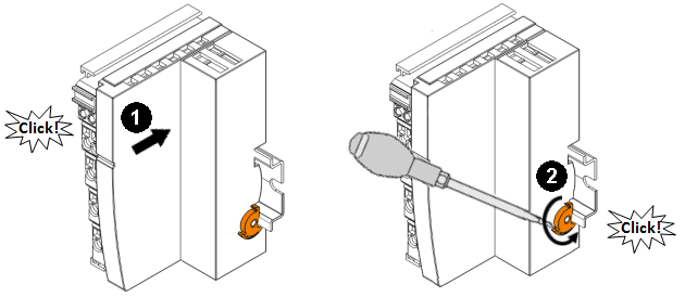
- First, plug the EtherCAT EJ Coupler onto the mounting rail.
- Position the rear connector of the EtherCAT EJ Coupler such that it is connected to the corresponding socket on the signal distribution board.
- Lightly press the EtherCAT EJ Coupler onto the pre-mounted mounting rail on the signal distribution board until the latch audibly clicks into place on the mounting rail. The required contact pressure and a safe connection to the signal distribution board is not established until the EtherCAT EJ Coupler firmly snaps onto the mounting rail.
- Use a screwdriver to push down the catch on the right-hand side, causing the catch to turn and engage audibly.
- During installation, ensure that the Coupler is securely latched to the mounting rail of the signal distribution board! The consequences of inadequate contact pressure include:
- loss of quality of the transferred signals,
- increased power dissipation of the contacts
- impairment of the service life
Mounting the EtherCAT Terminals (ELxxxx and CXxxxx Bus Coupler)
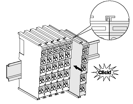
- Attach the Bus Terminals on the left-hand side of the EtherCAT EJ Coupler.
- Join the components with slot and key and push the terminals against the mounting rail, until the lock clicks onto the mounting rail.
If the terminals are clipped onto the mounting rail first and then pushed together without slot and key, the connection will not be operational! When correctly assembled, no significant gap should be visible between the housings. - In the final step, mount the Embedded PC (CXxxxx). Please refer to the corresponding documentation for the Embedded PC!
 | Fastening of mounting rails The locking mechanism of the terminals and couplers protrudes into the profile of the mounting rail. When installing the components, make sure that the locking mechanism doesn't come into conflict with the fixing bolts of the mounting rail. For fastening mounting rails with a height of 7.5 mm under the terminals and couplers, use flat fastening components such as countersunk head screws or blind rivets. |
Disassembly
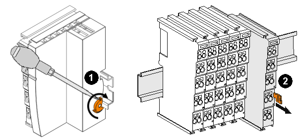
- Release the catch to remove the EtherCAT EJ Coupler. Push the catch forward with a screwdriver.
- Each terminal is secured by a lock on the mounting rail, which must be released for disassembly:
- Pull down the terminal at its orange-colored straps from the mounting rail by approx. 1 cm. The rail locking of this terminal is automatically released, and you can now pull the terminal out of the Bus Terminal block with little effort.
- To do this, grasp the unlocked terminal simultaneously at the top and bottom of the housing surfaces with your thumb and index finger and pull it out of the Bus Terminal block.
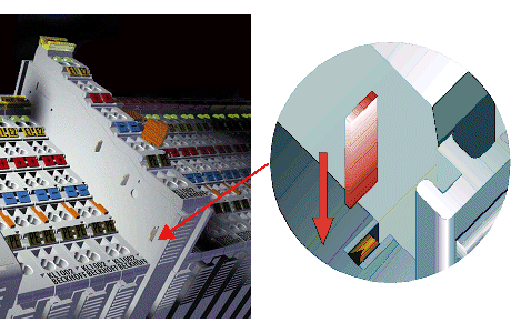
Connections within a bus terminal block
The electric connections between the Bus Coupler and the Bus Terminals are automatically realized by joining the components:
- The six spring contacts of the K-Bus/E-Bus deal with the transfer of the data and the supply of the Bus Terminal electronics.
- The power contacts deal with the supply for the field electronics and thus represent a supply rail within the bus terminal block. The power contacts are supplied via terminals on the Bus Coupler (up to 24 V) or for higher voltages via power feed terminals.
| Power Contacts During the design of a bus terminal block, the pin assignment of the individual Bus Terminals must be taken account of, since some types (e.g. analog Bus Terminals or digital 4-channel Bus Terminals) do not or not fully loop through the power contacts. Power Feed Terminals (KL91xx, KL92xx or EL91xx, EL92xx) interrupt the power contacts and thus represent the start of a new supply rail. |
PE power contact
The power contact labeled PE can be used as a protective earth. For safety reasons this contact mates first when plugging together, and can ground short-circuit currents of up to 125 A.
Note that, for reasons of electromagnetic compatibility, the PE contacts are capacitatively coupled to the mounting rail. This may lead to incorrect results during insulation testing or to damage on the terminal (e.g. disruptive discharge to the PE line during insulation testing of a consumer with a nominal voltage of 230 V). For insulation testing, disconnect the PE supply line at the Bus Coupler or the Power Feed Terminal! In order to decouple further feed points for testing, these Power Feed Terminals can be released and pulled at least 10 mm from the group of terminals.
WARNINGThe PE power contact must not be used for other potentials!