Switching signal from a digital input of the EJ7411
This chapter describes the configuration exemplarily for the digital input "Input 1".
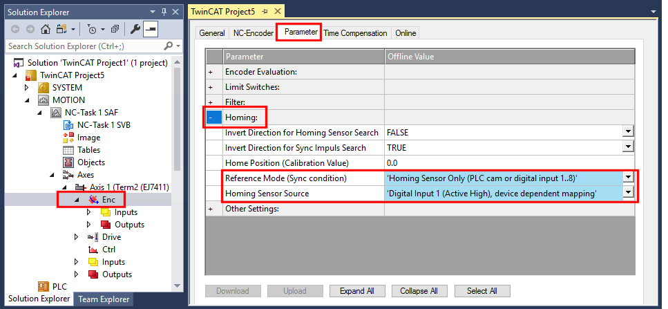
- 1. In the Solution Explorer:
click on NC axis > "ENC", open the tab "Parameters" and expand the section "Homing". - 2. Set the parameter "Reference Mode" to "Homing Sensor Only (PLC cam or digital input 1..8)".
- 3. Set the parameter "Homing Sensor Source" to "Digital Input 1 (Active High), device depending mapping".
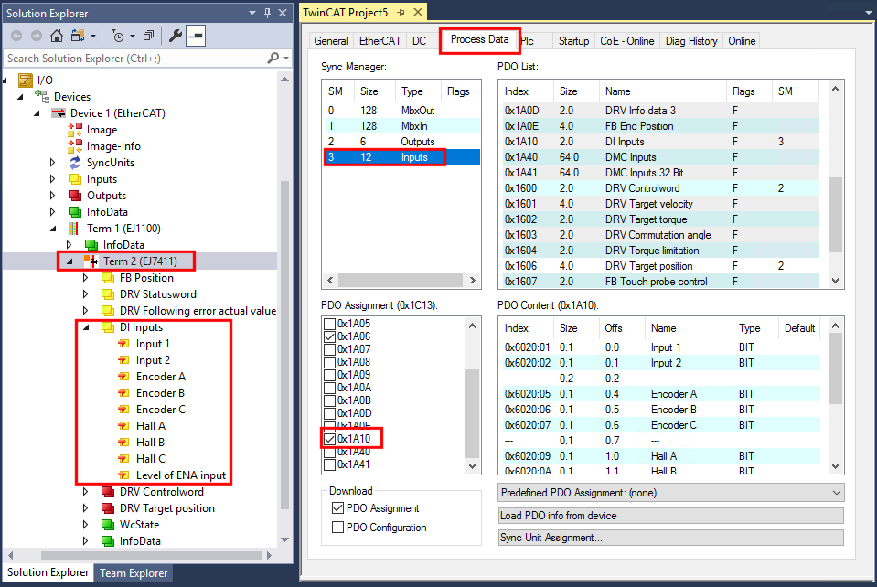
- 4. In the Solution Explorer:
click on the EJ7411, open the "Process Data" tab, select the Sync Manager 3 "Inputs" and activate the PDO Assignment 0x1A10. - The process data object "DI Inputs" is activated.
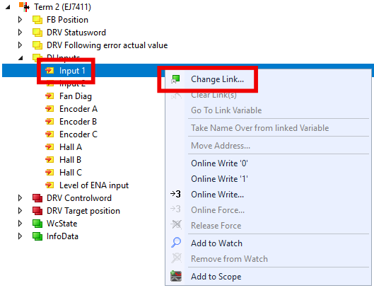
- 5. EJ7411 > "DI Inputs" > right click "Input 1", select "Change Link".
- A dialog box appears.
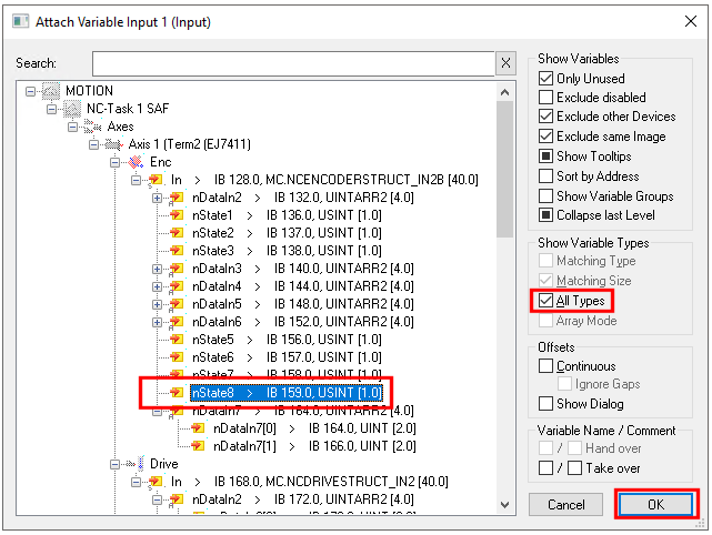
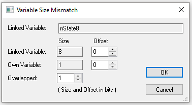
- 6. Click on "All Types", select the variable "nState8" and confirm with "OK".
- A dialog box appears.
- 7. Confirm with "OK".
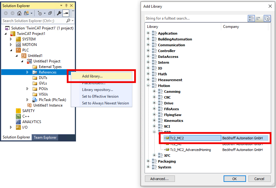
- 1. Add the library "Tc2_MC2" to the PLC project:
Navigate to PLC > "References", right click, "Add Library..." - 2. Insert an instance of the function block "MC_Home" from "Tc2_MC2" library in the PLC.
- 3. Do not connect the input "bCalibrationCam".
- You can start homing with a positive edge at input "Execute".