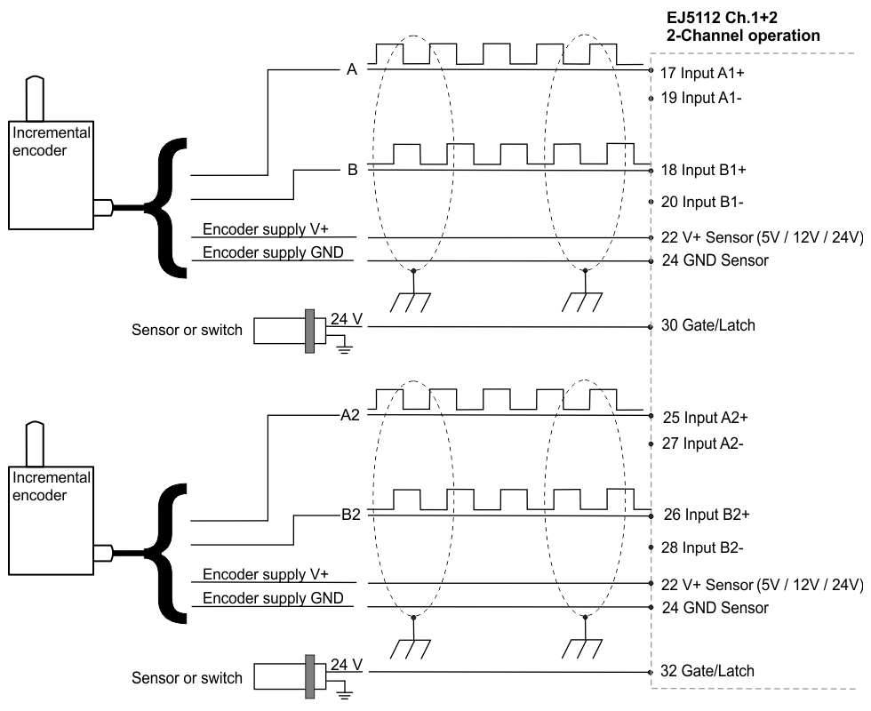
TTL mode
Connection of TTL encoders without zero pulse in two-channel mode
 | Connection instructions
|
Connection of TTL counters / pulse generators without zero pulse in two-channel mode
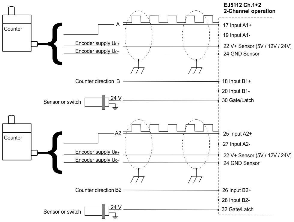
| Connection instructions
|
| Connection instructions
|
| Connection instructions
|