The following points should be considered during design phase and installation:
 | Notes for routing and installation - The encoder supply is connected externally, e. g. via the power supply plug-in module EJ9505.
- The BiSS and SSI information (Clock and Data) are transmitted as differential signals. To ensure a good EMC immunity, also for long distances, shielded cables with twisted pair conductors should be used.
- The cable shield should be connected to earth at both channel ends and the two end devices should be always at the same reference potential.
- When using externally shielded cables, particular care should be paid, not to damage or to interrupt the shield itself.
- Shield should be connected near by the connector.
- Refer also to the corresponding notes of the sensor manufacturer!
- Refer to the guide lines in the design guide for the EtherCAT plug-in modules to ensure a proper routing of the differential signals!
- The value of each termination resistor should be equal to the cable characteristic impedance, typically 120 Ω for EIA-485 or RS-485 standard.
- Routing of the differential signals should be impedance controlled with typically 120 Ω for EIA-485 or RS-485 standard. Traces wide should be > 0.2 mm, the maximum ampacity need to be taken into account.
- To improve the EMC immunity it may be helpful to connect the two signal channels on two different connectors.
|
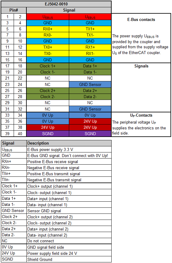 Fig.8: EJ5042-0010 - Pinout